 This site is under construction!
This site is under construction!
Dr. Meter PS-305DM Power Supply Repair
Repair of a Dr. Meter PS-305DM Power Supply
Where to start with this one...
The first one I got came from Amazon with the polarity of the outputs inverted.
The company would not believe me.
I sent a video of my multimeter showing the polarity was backwards, and "my multimeter must be bad".
So I tried another one. Same response.
So I sent a compilation of videos showing LEDs only lighting up in one direction, showing electromagnets only working in reverse, showing electrolysis only working "backwards", and...
FINALLY they took the RMA and replaced the unit with the one that is the subject of this repair.
This one worked well for a couple of years, for all sorts of tasks.
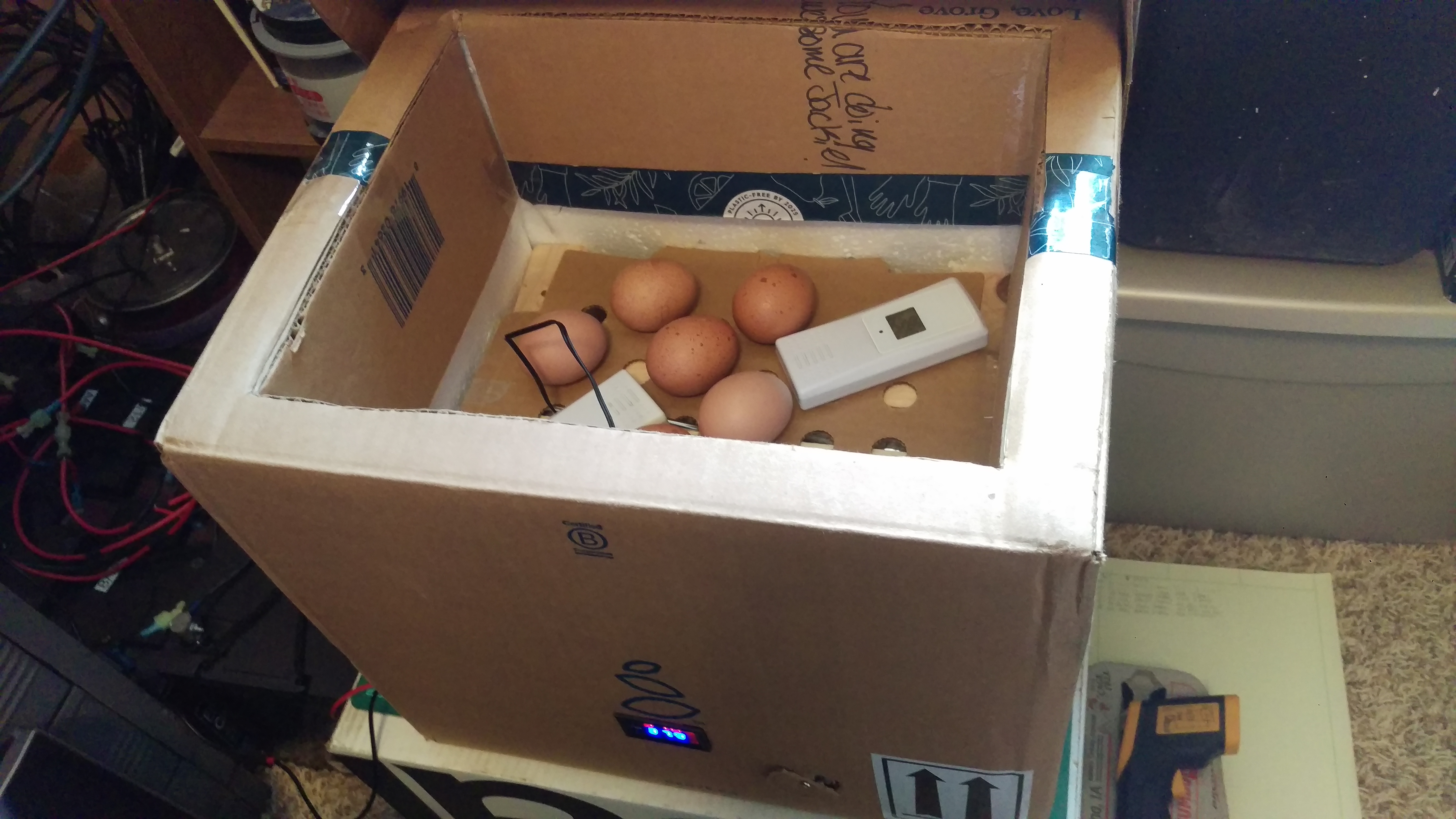
But when I built a 12vDC Egg Incubator (note to self; upload that project too), it lasted a grand total of 2 weeks under 24/7 load.
The incubator used a digital thermostat and relay to switch power to a ~50-Watt heating element and fan, which drew about 4.5A at 12.8vDC (nominally within the capacity of this power supply). And it's current-limiting, so what could go wrong? /s
The failure mode... well it could have been really bad.
The PS-305dm lost all voltage regulation, and the current regulation would activate but have no effect.
The meter was pegged at about 35 volts and would deliver more current than I wanted to test out.
It fried every electronic in the incubator except the heating element itself.
Luckily the relay/thermostat control board burnt out in such a way that it didn't set anything on fire, and we got four out of the six eggs to hatch without issue (after a hasty late-night hot swap repair), and I put the repaired incubator on the 12vDC solar (which I should have probably done in the first place).
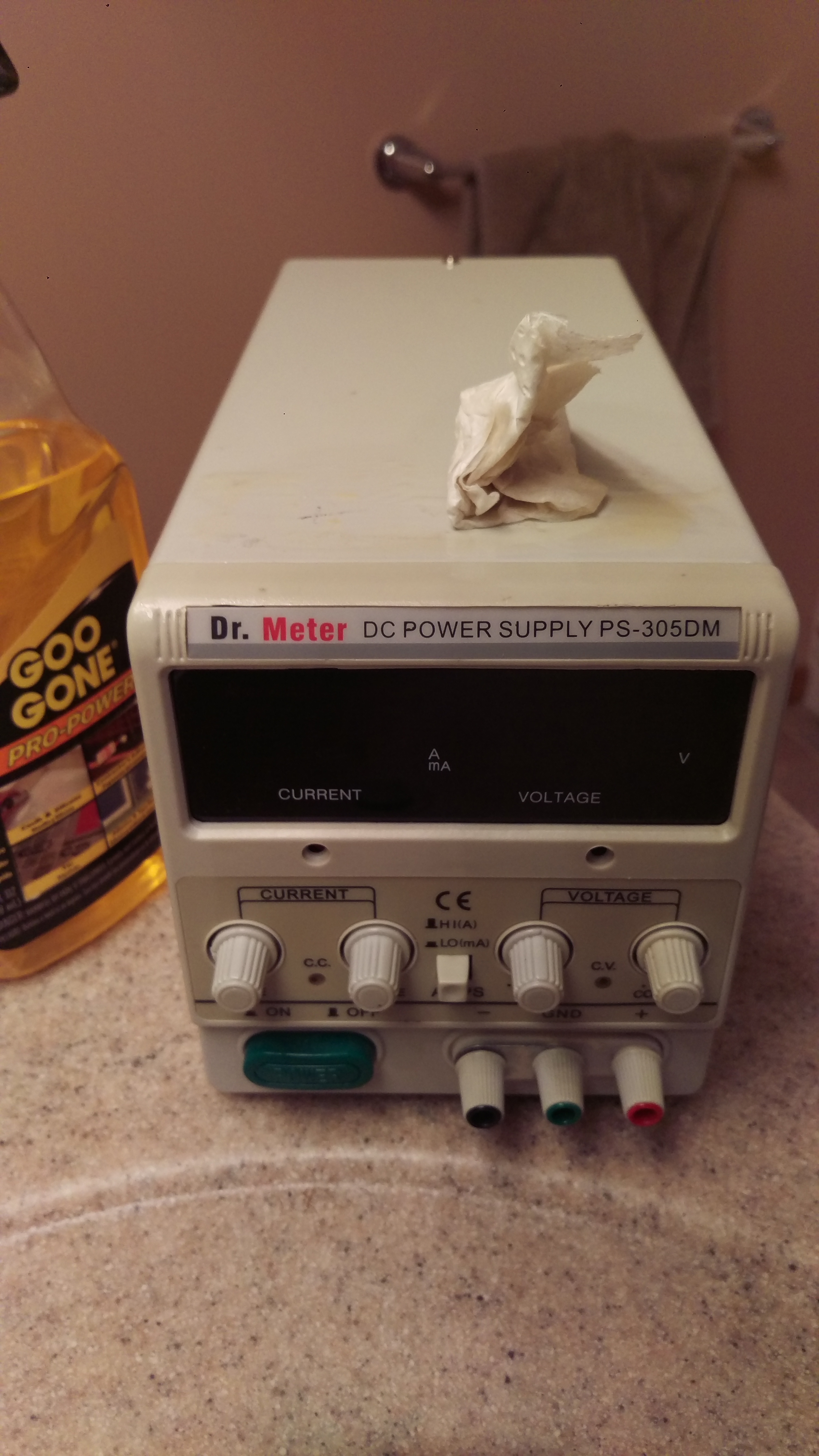
I got it to work, and here's a pic of the Goo-Gone I've been trying to use to get the "FIX THIS" tape-label off.
The incubator in question (post-catastrophe, running just fine on my solar bank)
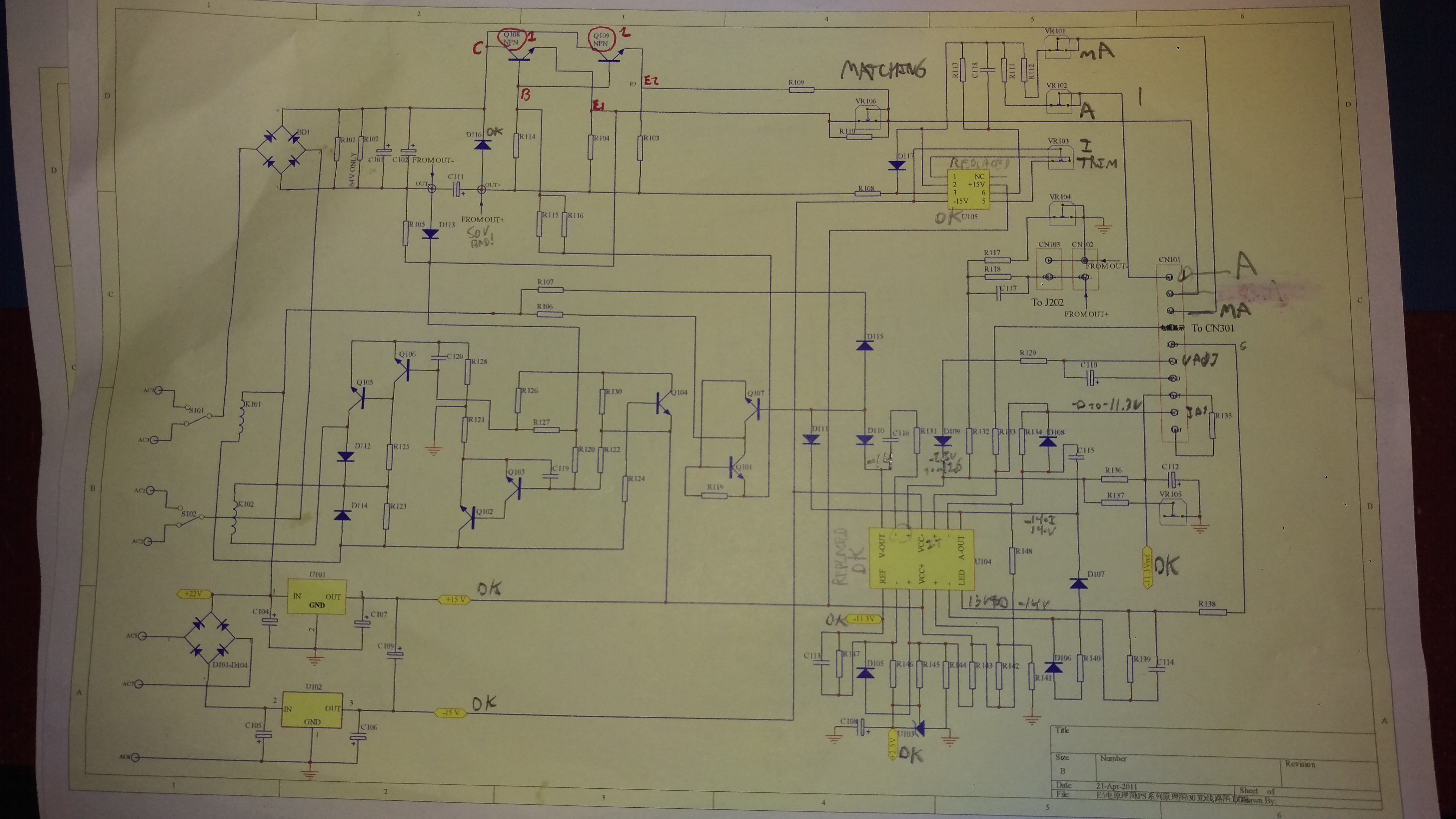
I found schematics for this power supply from pieraisa at his site here, which I highly recommend: https://www.pieraisa.it/php/myHwProjects.html
There, Pierasia had the following files, rehosted here:
PS305D_Schematic_Main.pdf
PS305D_Schematic_Display.pdf
PS305D_Schematic_Controls.pdf
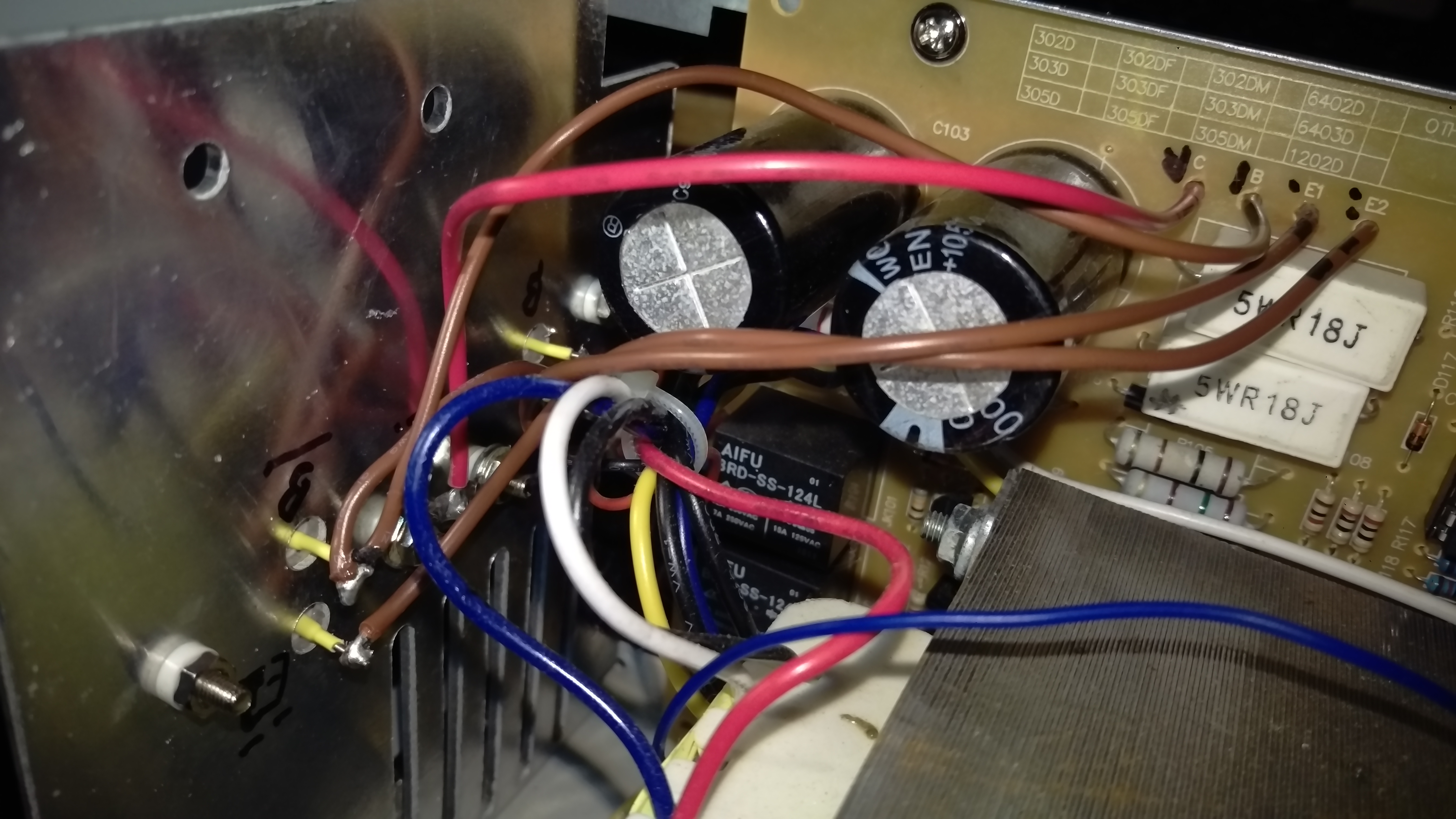
The first step was to go around and check the capacitors, all were good.
The next step was to check the 7815 and 7915 vregs (labeled), both good.
The third step was to check the other voltages and pins that I could determine, all looked good except the outputs.
I even went ahead and pulled the ICs and placed sockets in there, for ease of testing and future replacement if needed.
So that left the finals (circled in red). These were the issue.
These are 2N3055 NPN Bipolar Power Transistors
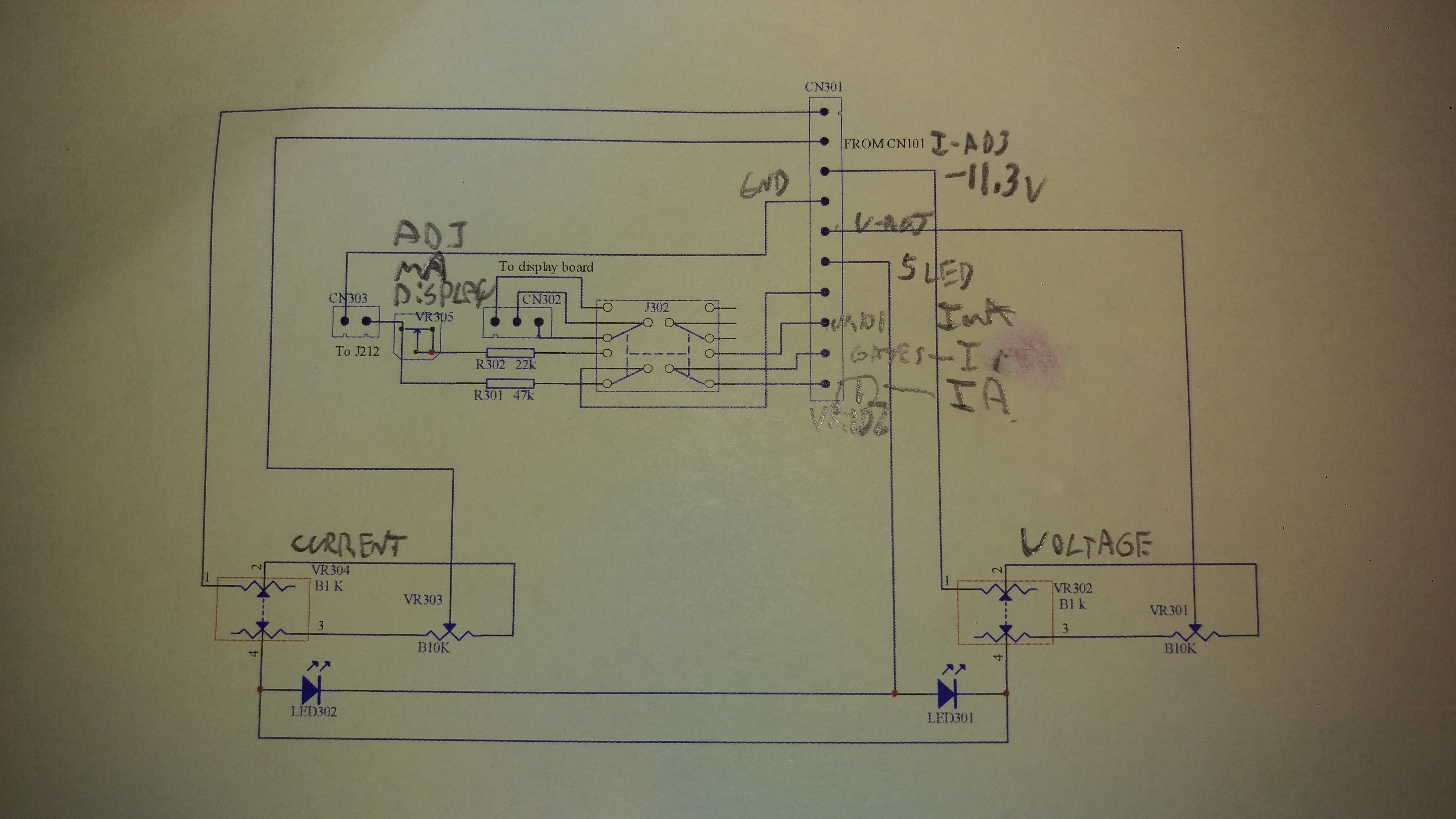
Schematic for the relay board, with some pins labeled.
The second 2N3055 had a near-dead short (~10 Ohms) between the Collector and Base. It should be in the megaohms. I replaced them both with new ones. Be sure to check for isolation between all conductors and the heatsink. I think the heatsink in this configuration was ultimately the problem, and I baked the old ones at near-capacity load.
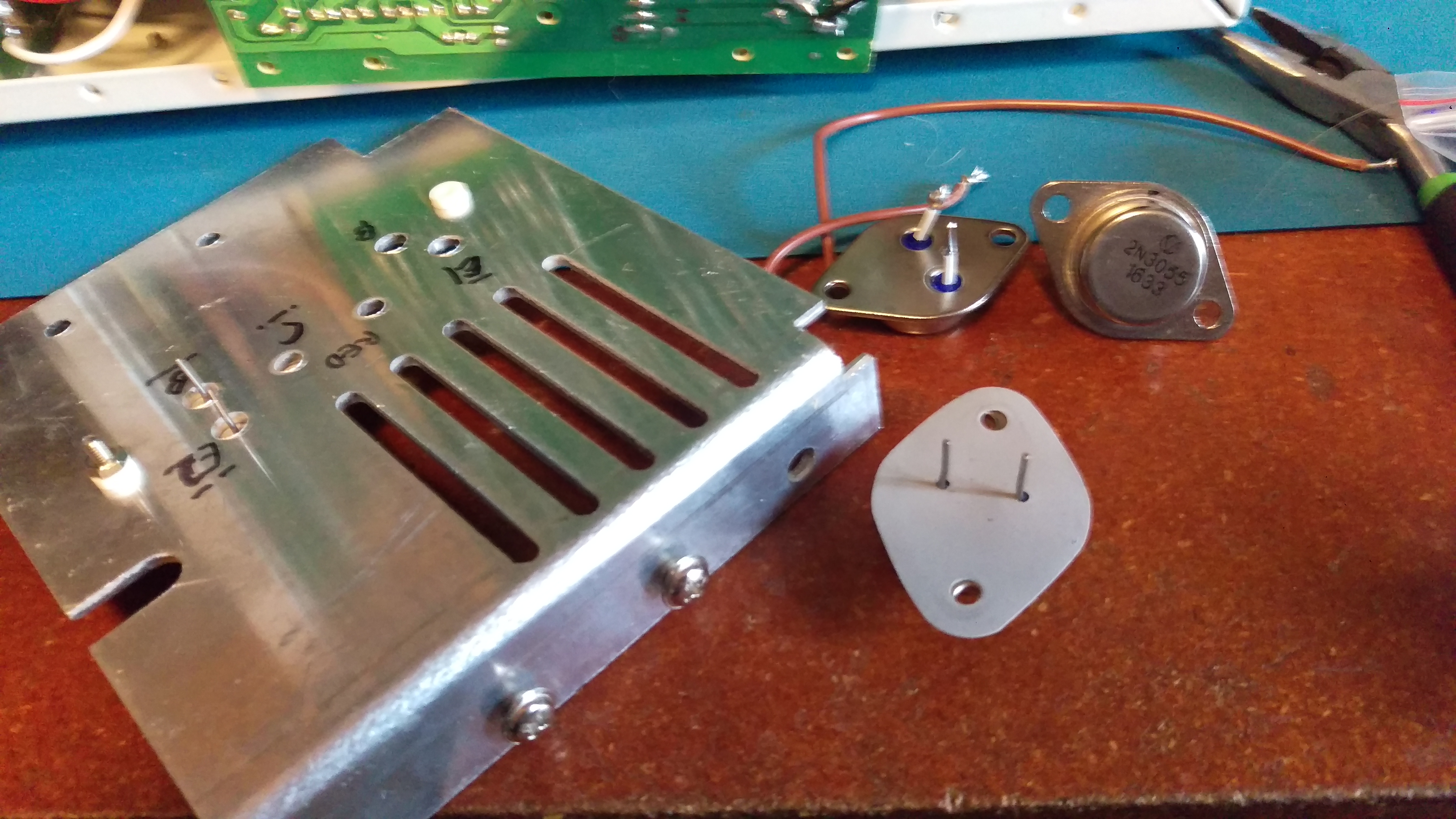
I labeled all conductors so I could put them back right (always a good idea).
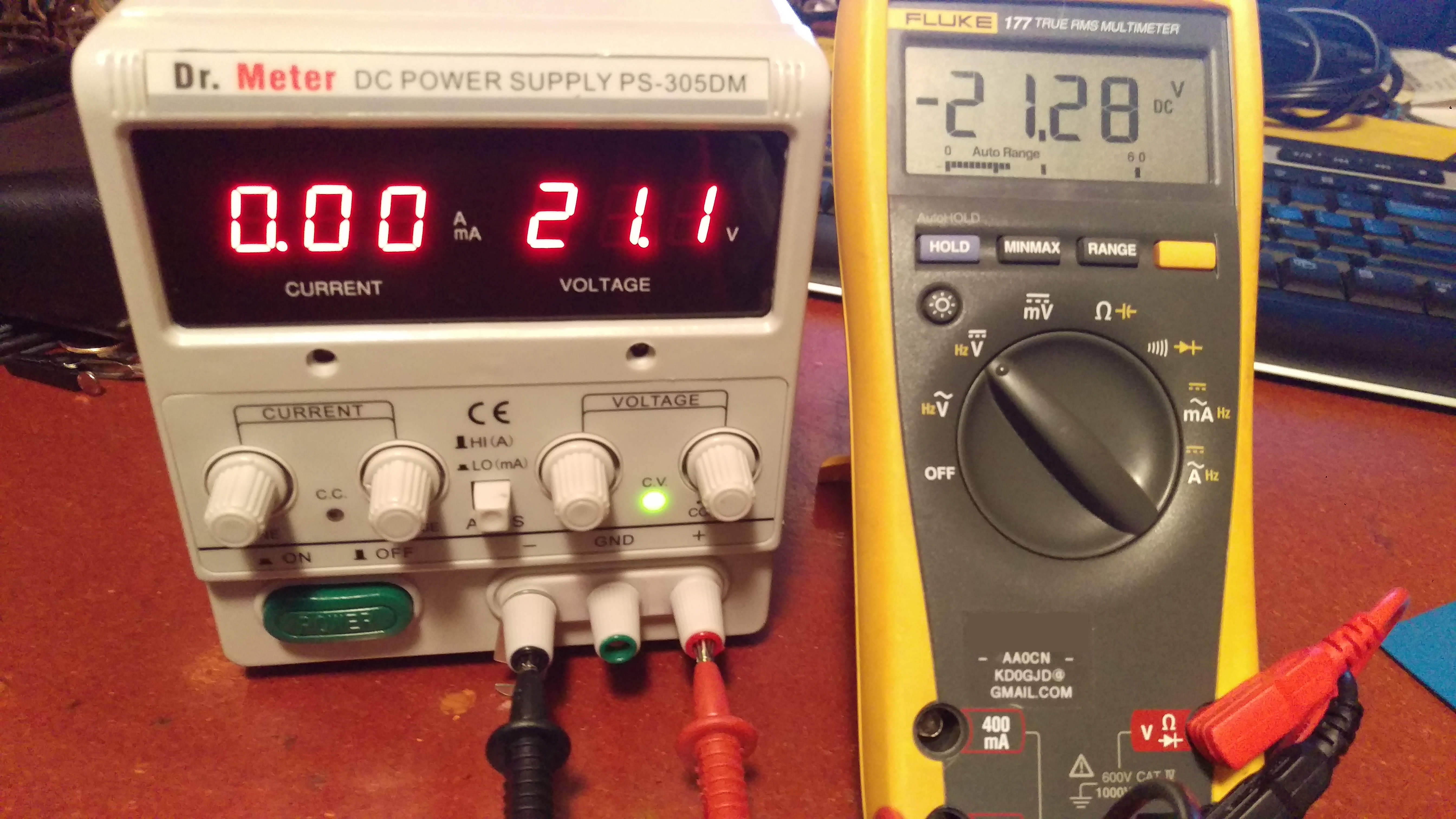
Next came testing and alignment.
I was happy to see the voltage and current back under reasonable control
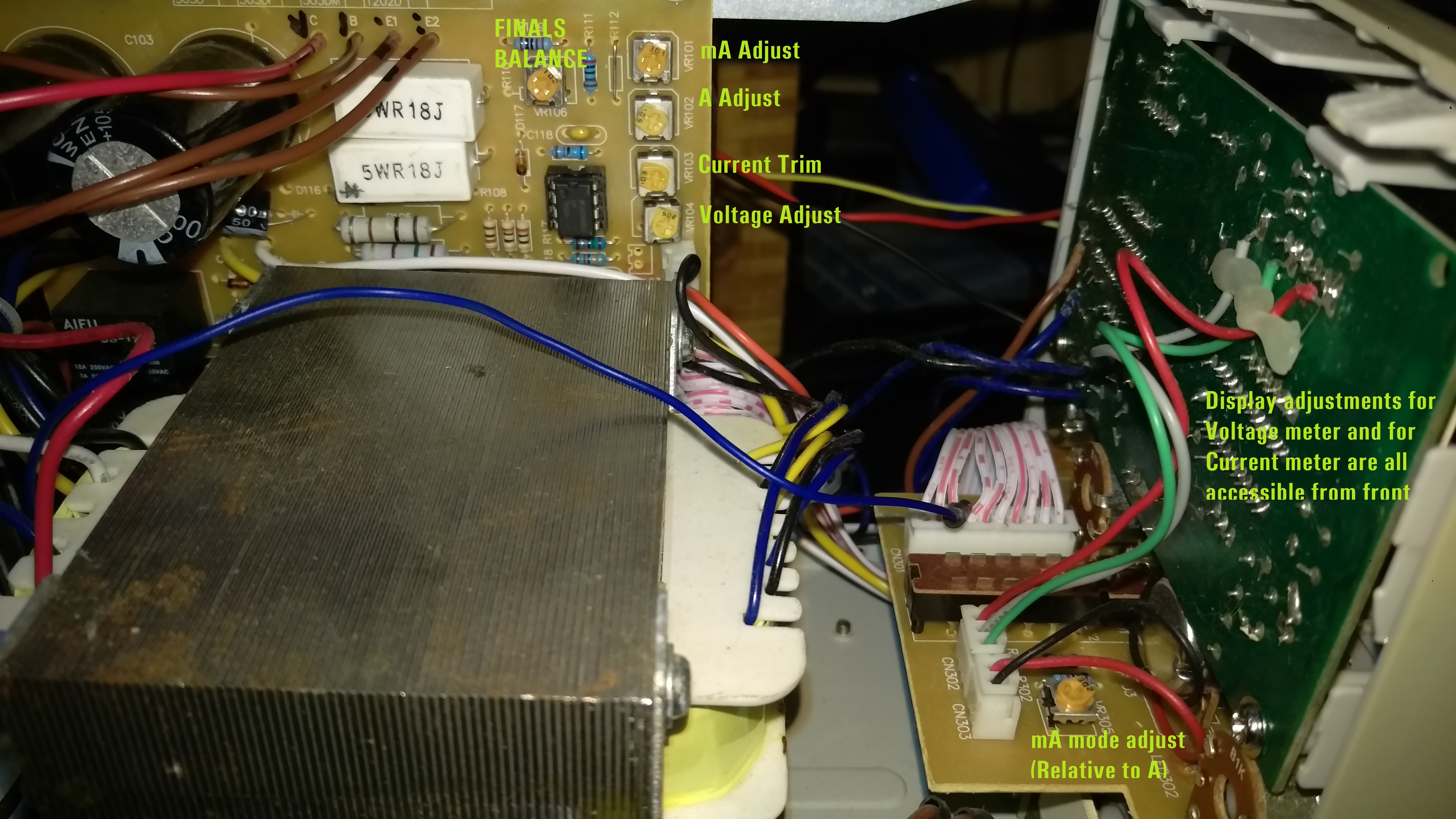
At this point it was kind of a guessing game exactly how to re-align this.
I started by balancing the voltage off of the finals with VR106 under load.
I then calibrated the voltage output.
I then went back and forth between the trimmers, the offsets, and the adjustments both in mA and A mode
There's certainly a "right" way to do this that isn't how I did it, but I kept tweaking until I was happy with the results compared to what by Fluke was telling me with respect to current output.
So far so good with the repair, but only time will tell if this repair (or more specifically, the design itself) holds up.
I won't be running it unattended with anything that might be catastrophic.
Well... not in the house anyway.
Click on the letter for WinLink Email!

2021 AA0CN