 This site is under construction!
This site is under construction!
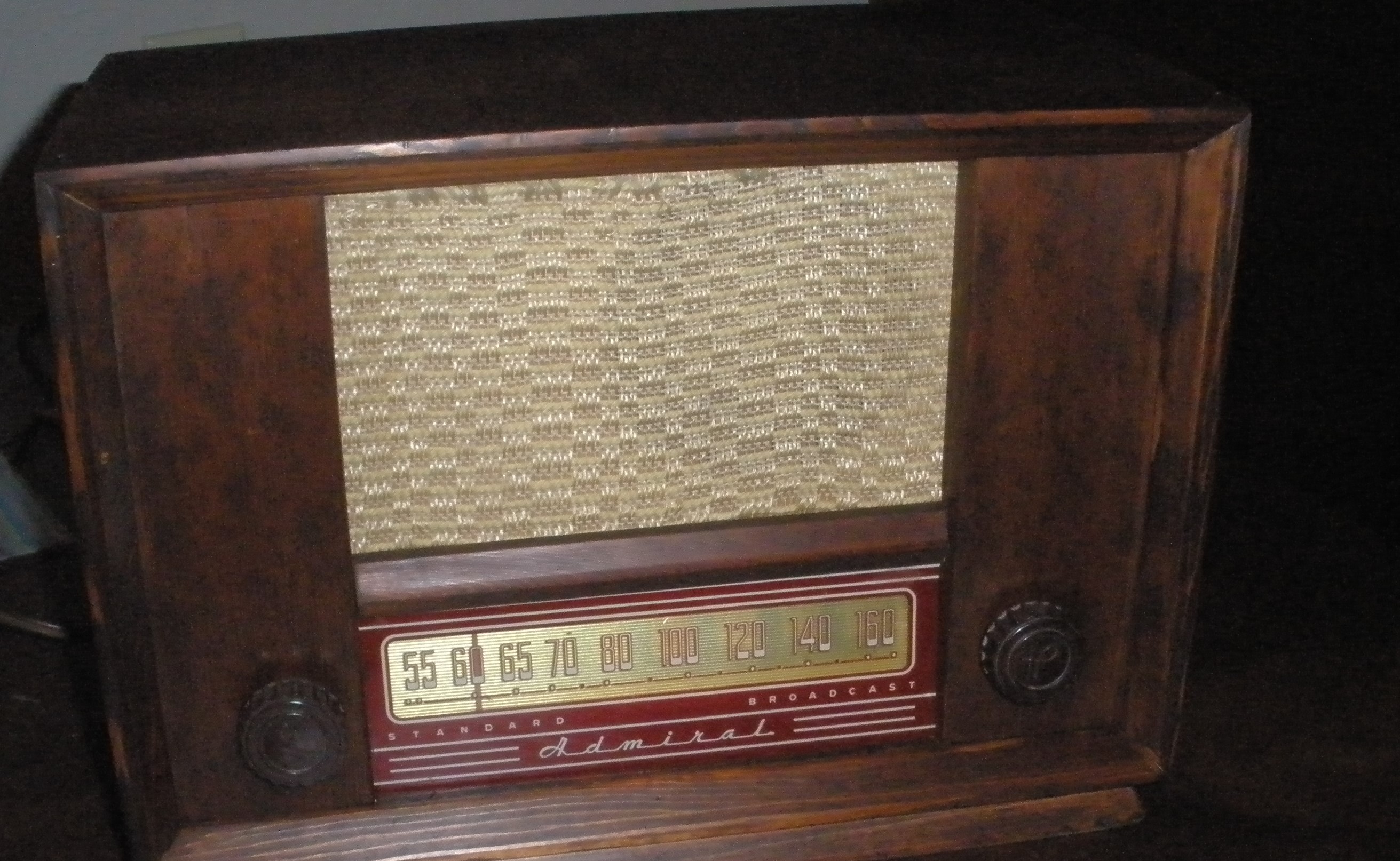
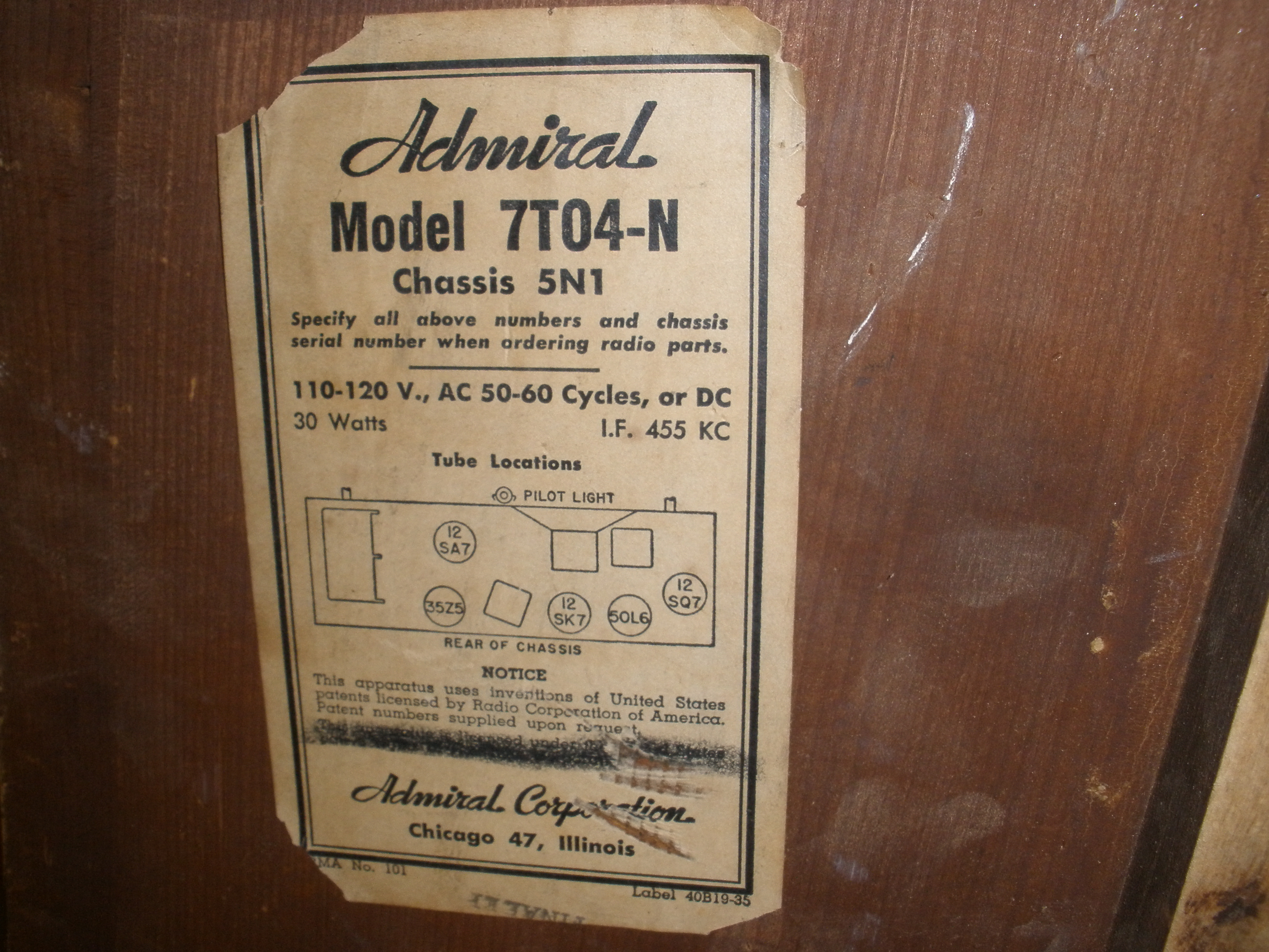
1948 Admiral 7T04-N 5N1
Full cabinet restoration and partial re-cap
This was my very first restoration of a vintage receiver.
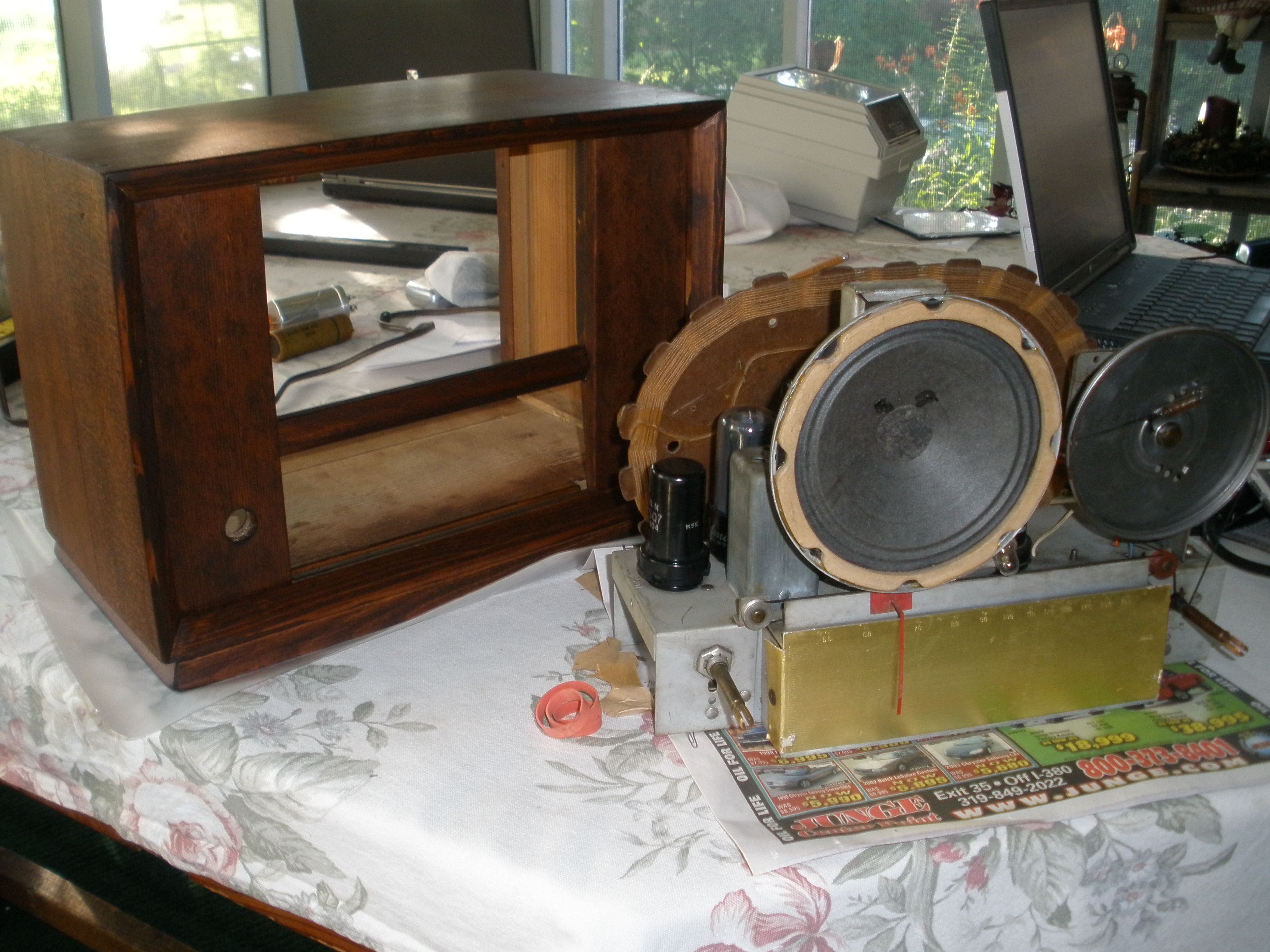
The "meat" of a 7T04 Admiral Radio, "America's Smart Set" as they were called during the great WW2.
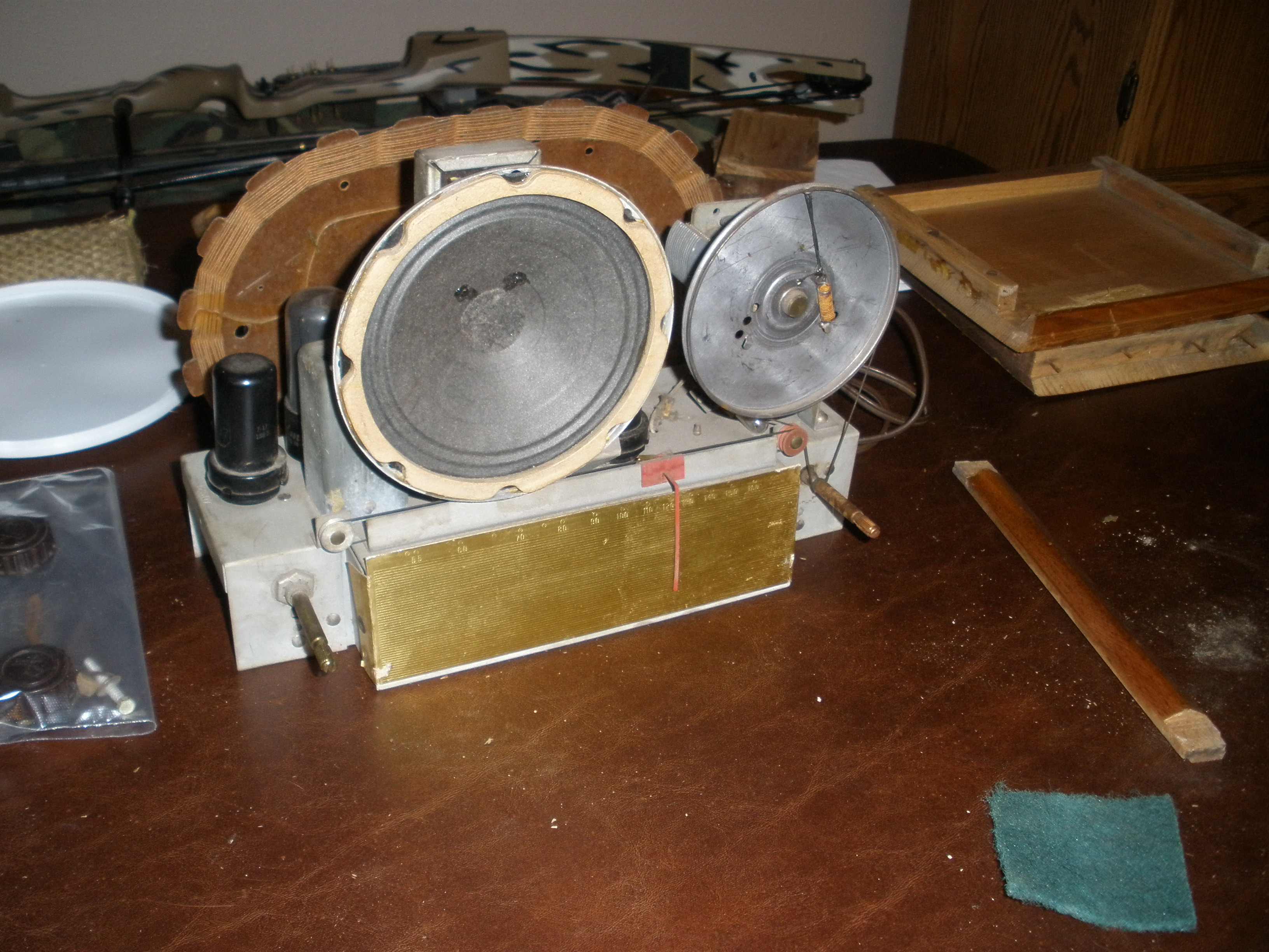
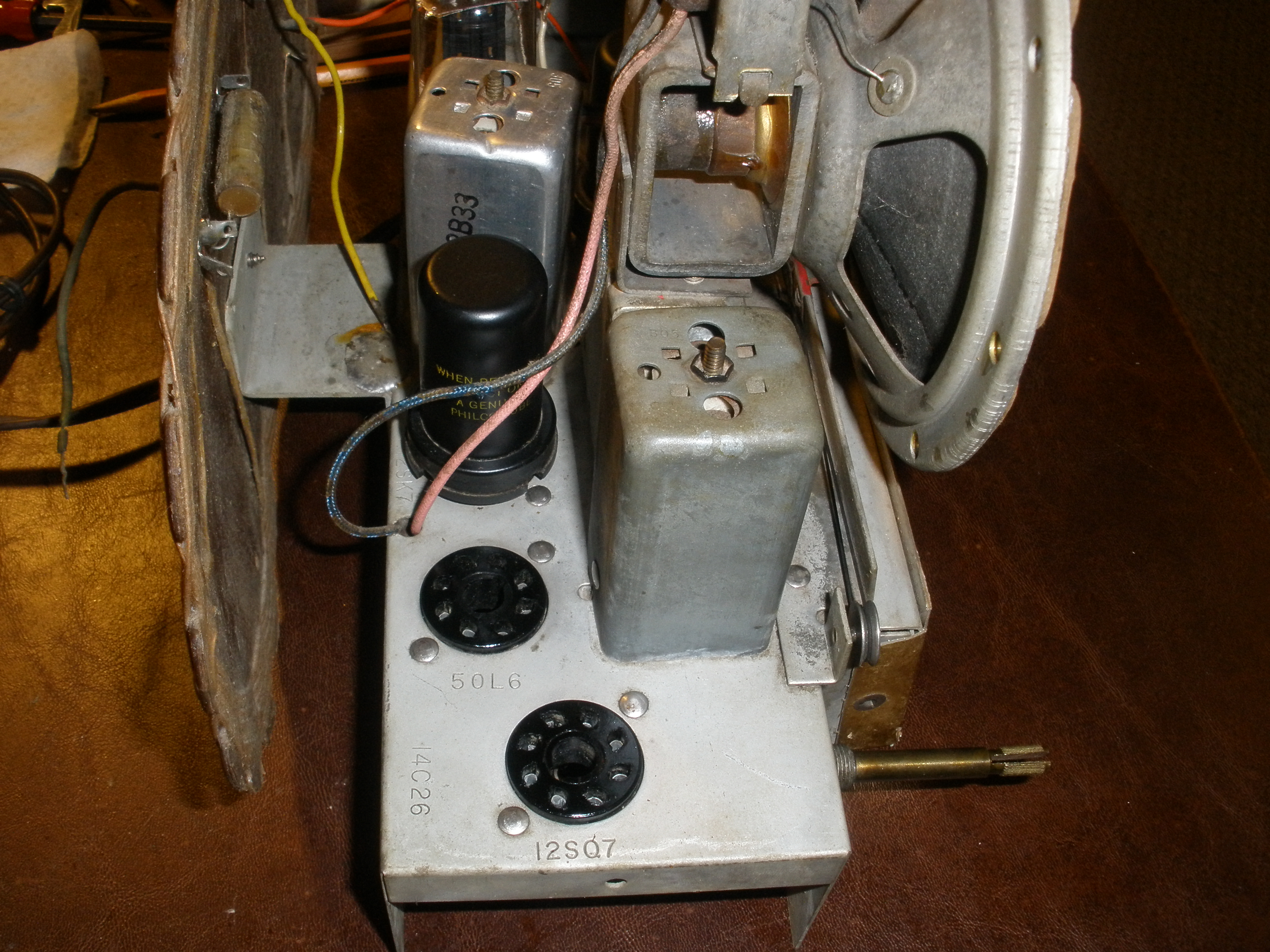
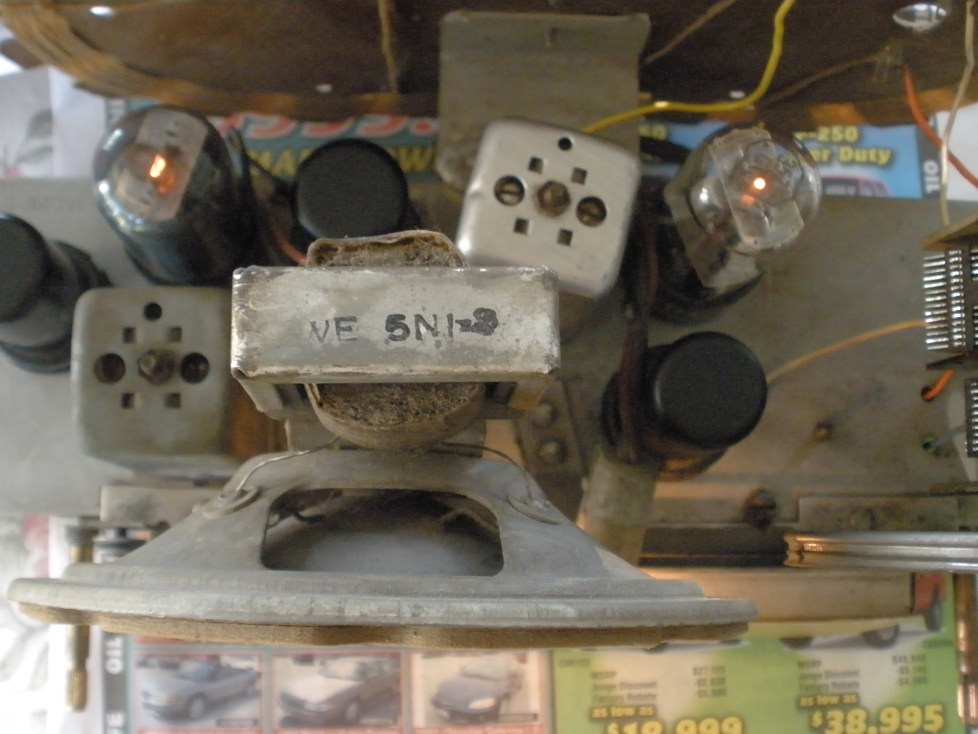
With the wooden case removed, we see the five tubes that power this beast, and might just have blasted Roosevelt's voice announcing the landings at Normandy, sitting on top of the radio's frame. The main power amp, a 50L6-GT, is smokey and obviously part of the reason the radio now only blasts a 60Hz buzz at full volume, all the time.
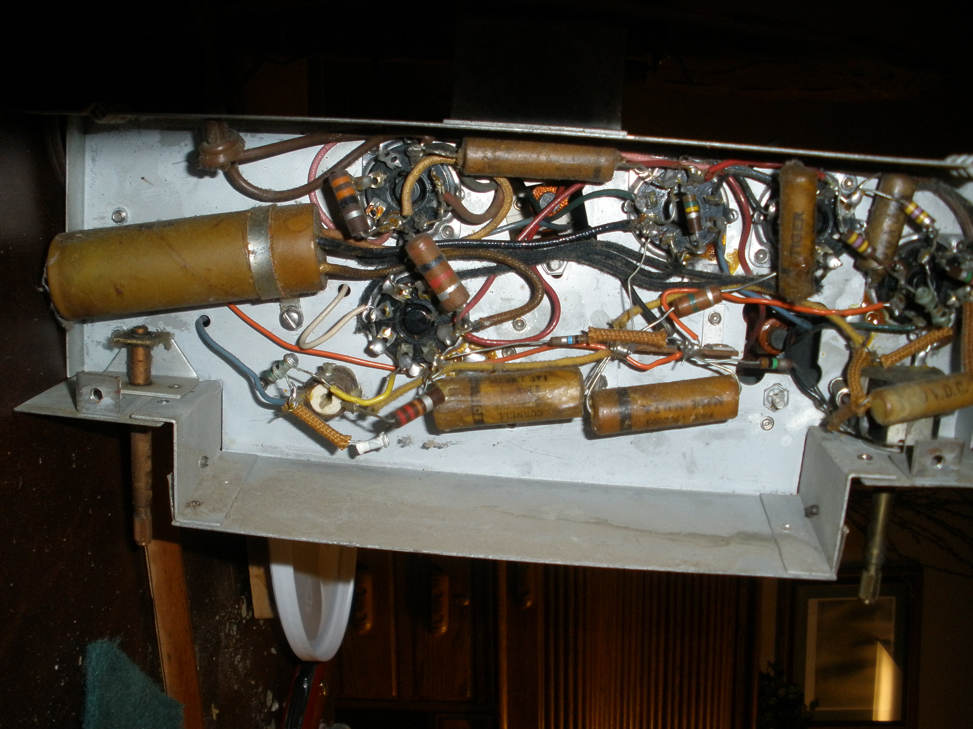
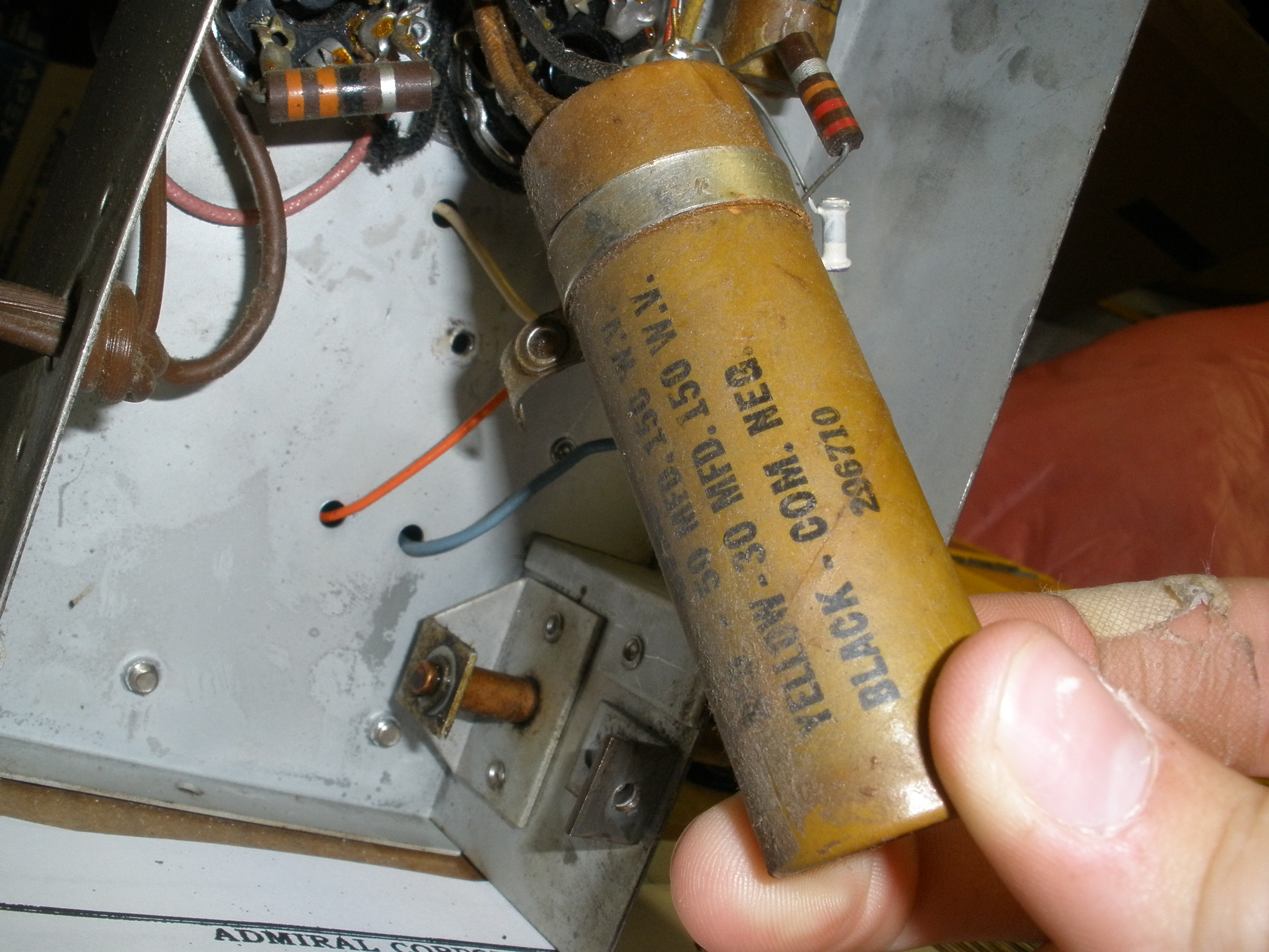
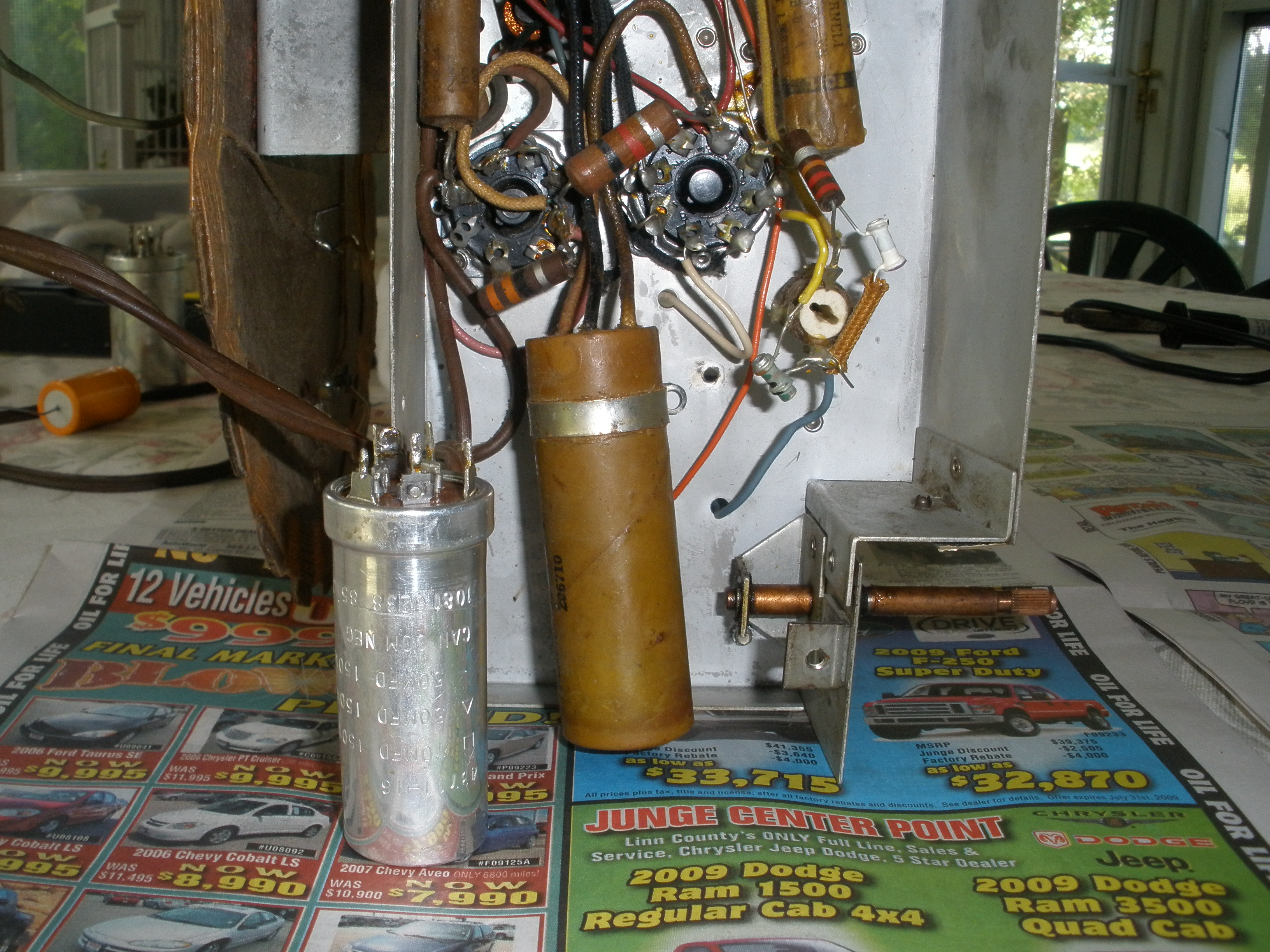
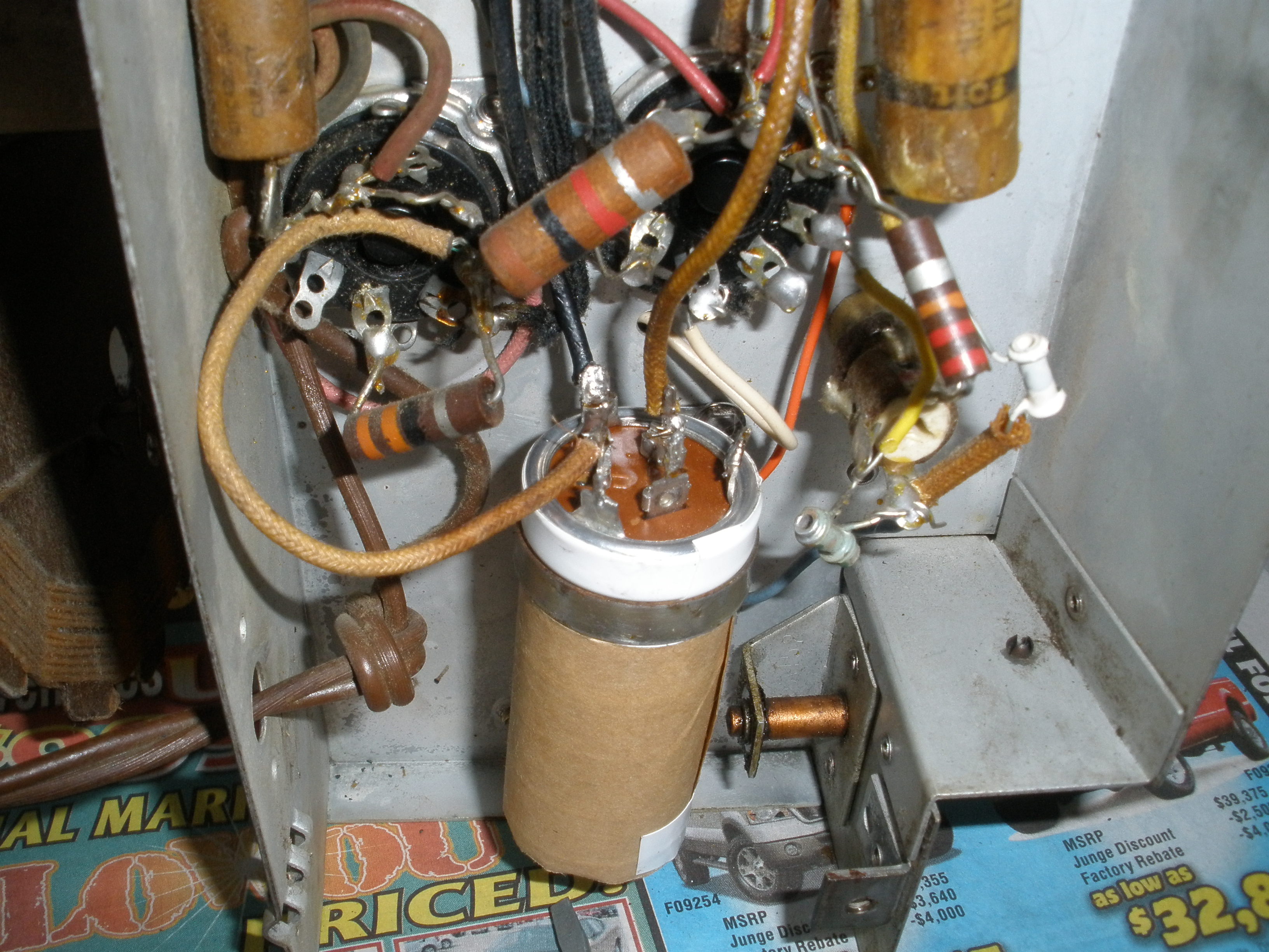
Here are the underworkings of the radio. You can see how difficult pre-plastic-coated-everythings were to work with. Check out those capacitors, or as all the schematics of the day called them, "condensers". And those resistors? Yeah, the valuing color bands look like they were hand-painted on, since they probably were.
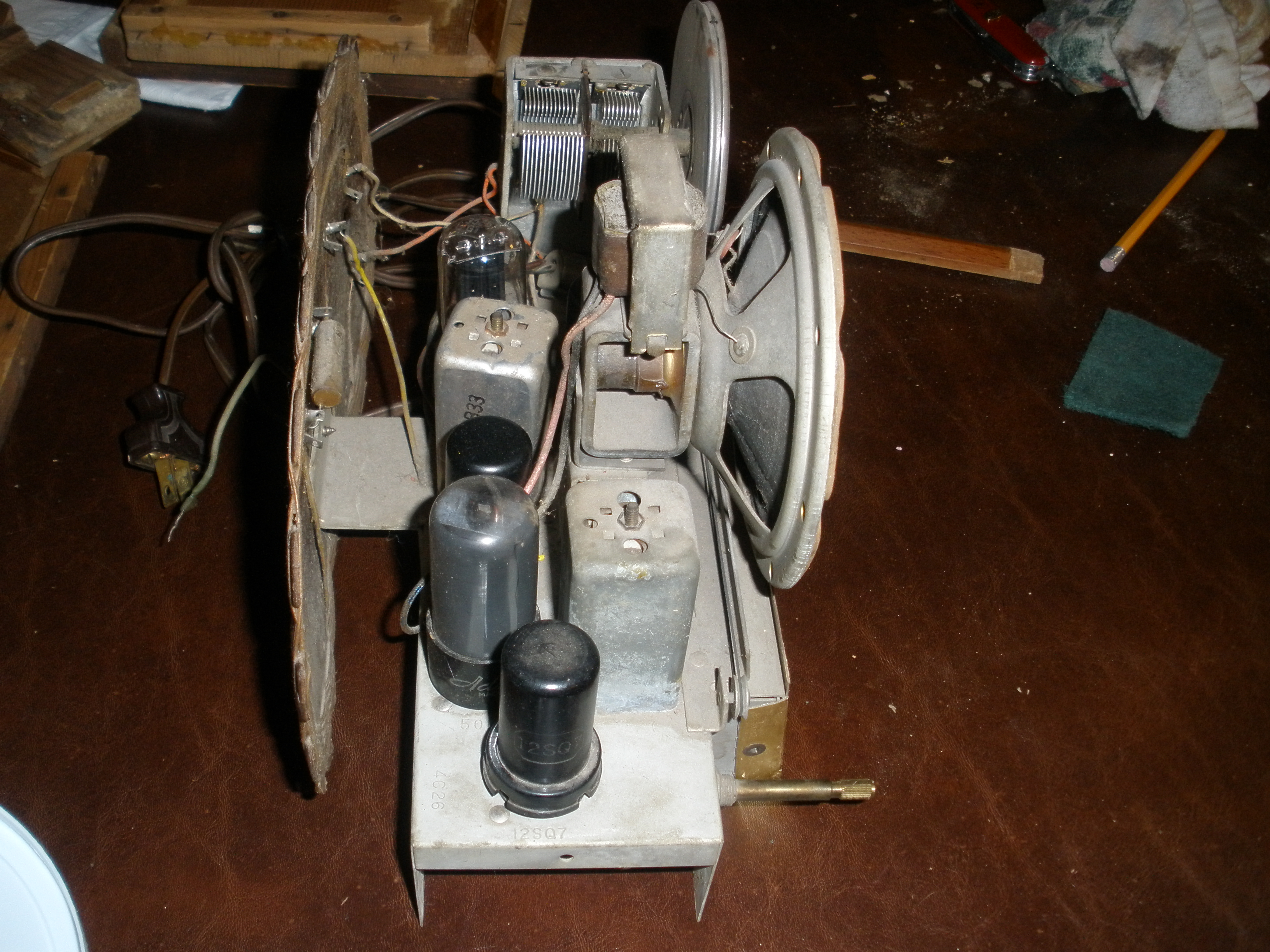
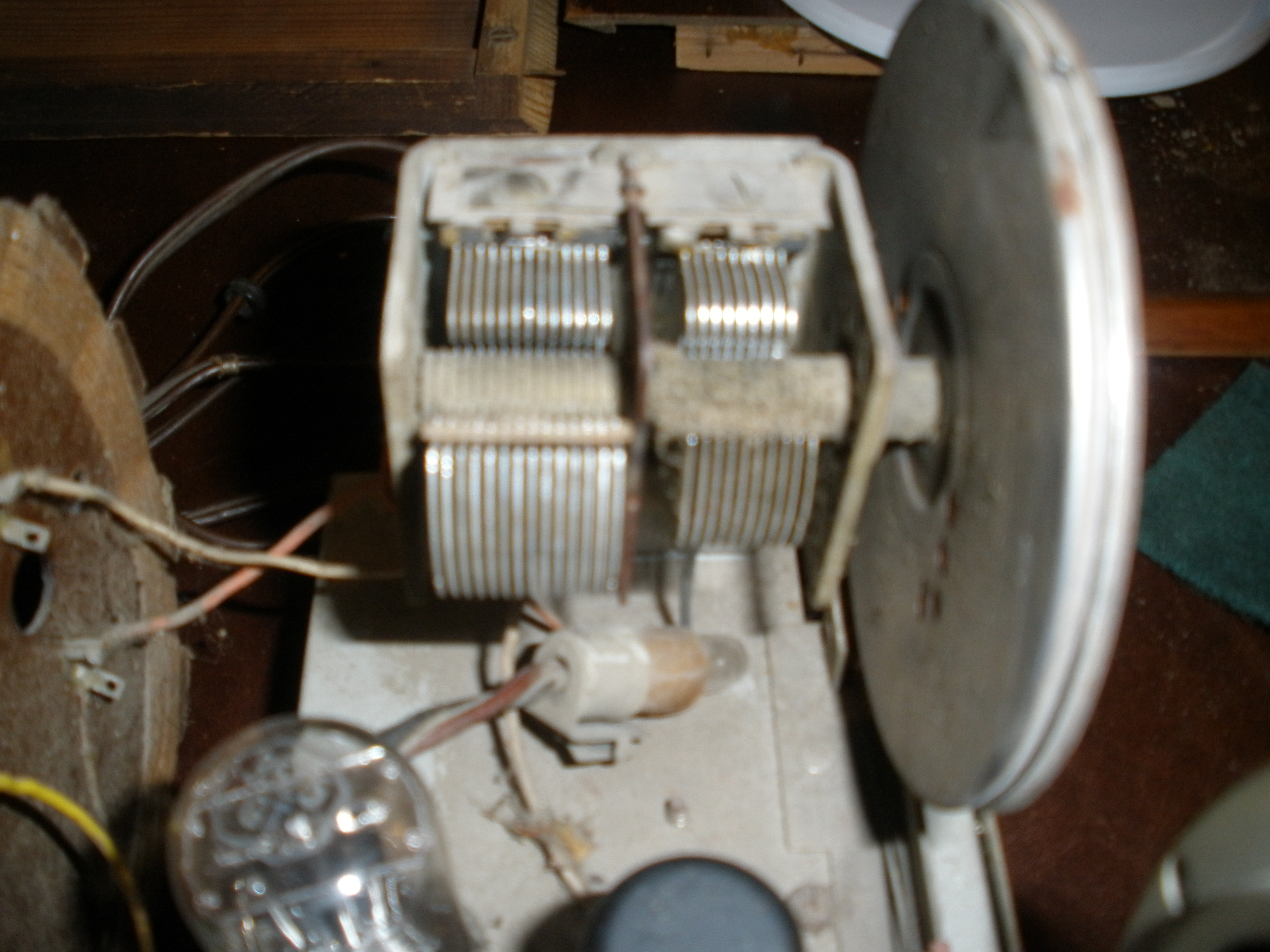
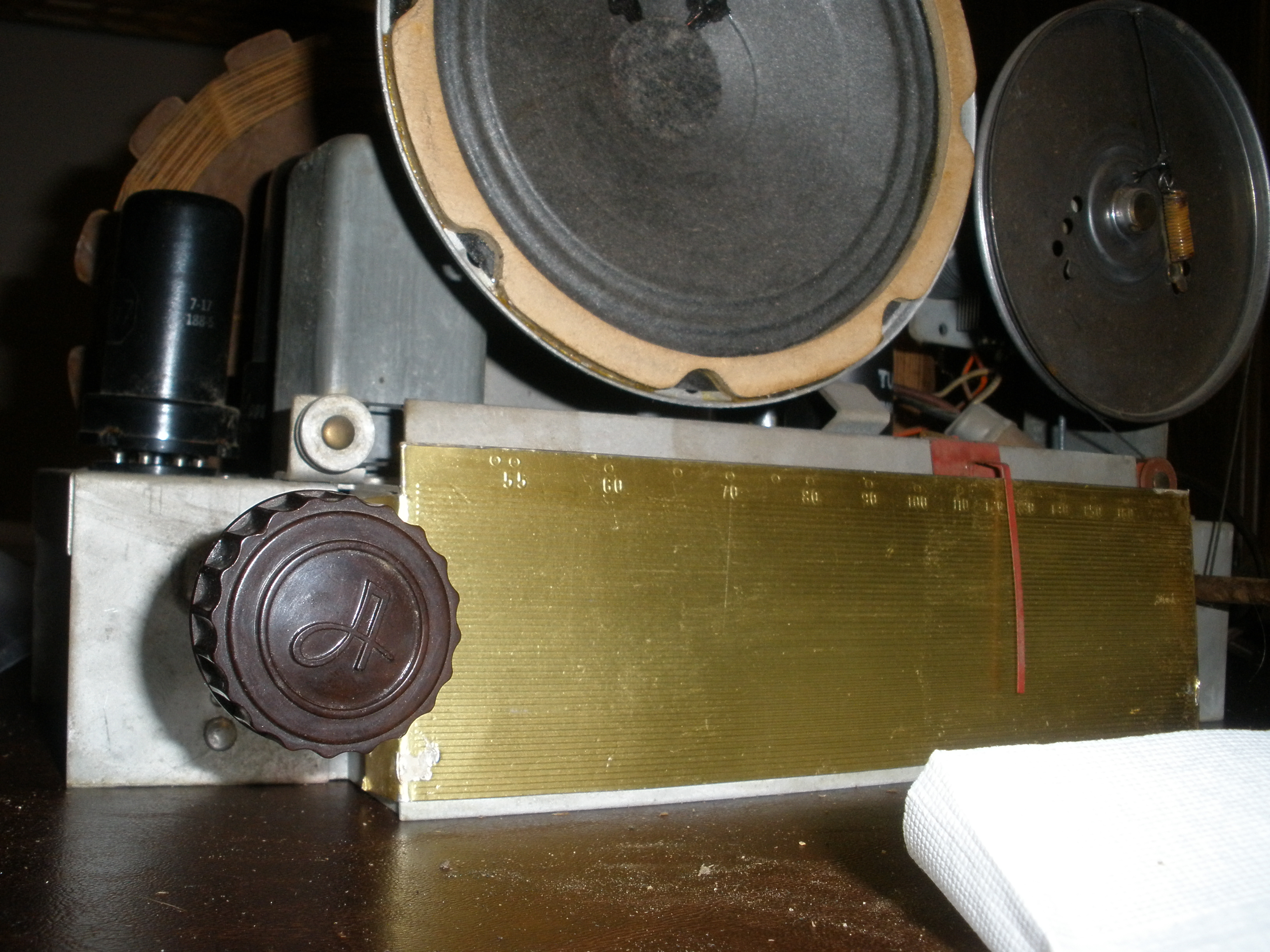
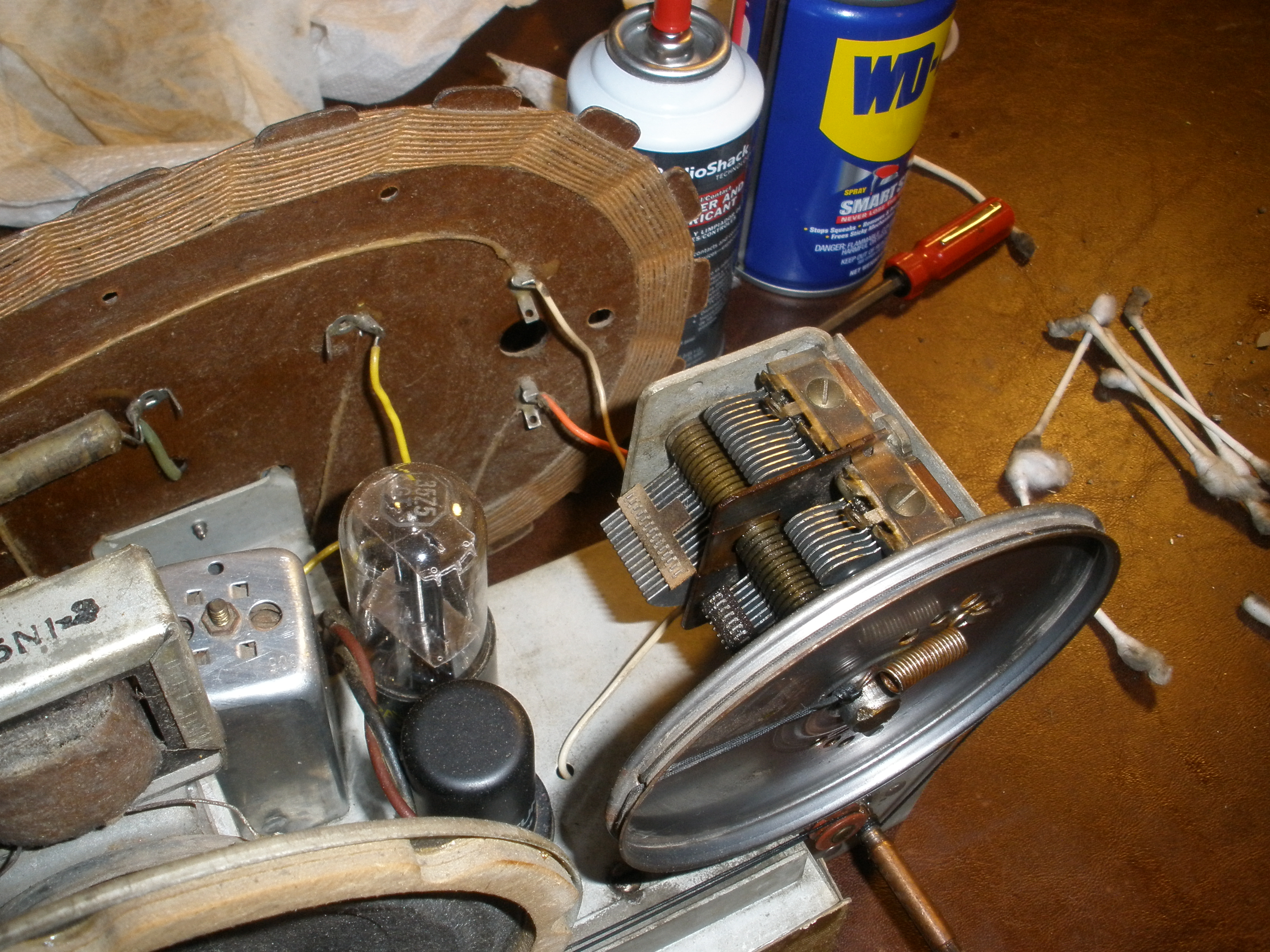
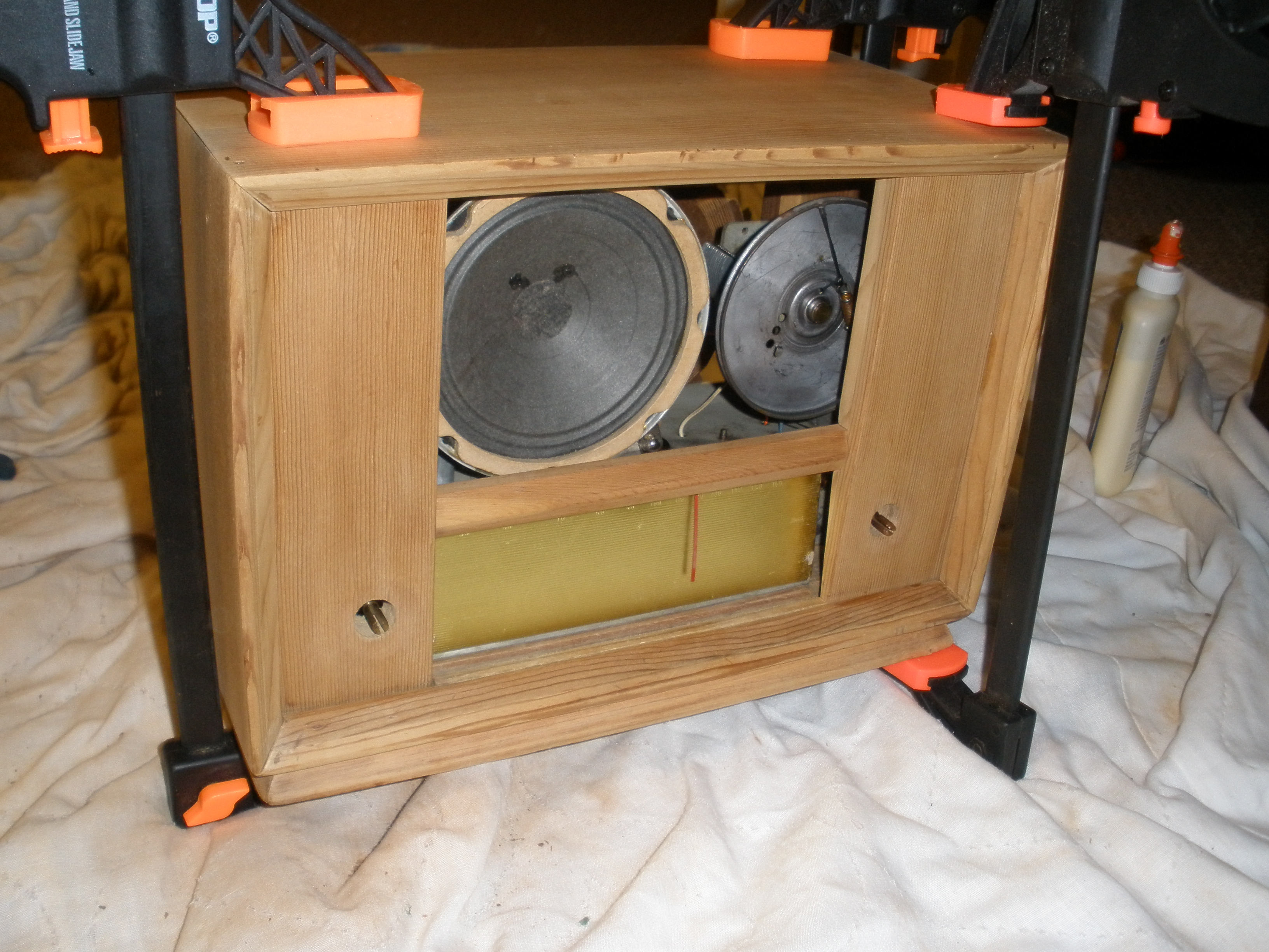
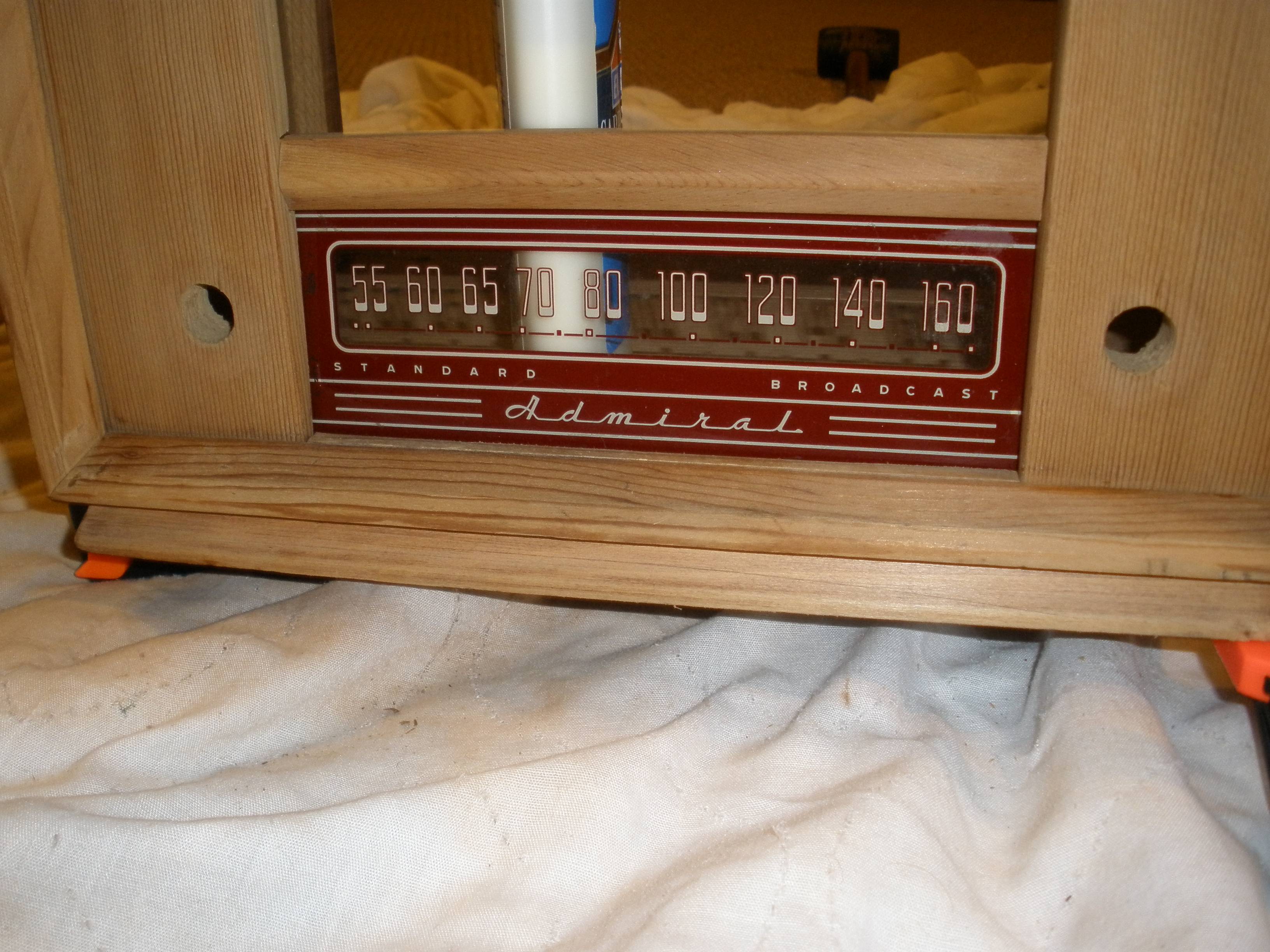
Here we see the speaker, the backplate and needle, and the wheel that turns those giant variable capacitors that will hone in on any AM station between 550 and 1600 KCs
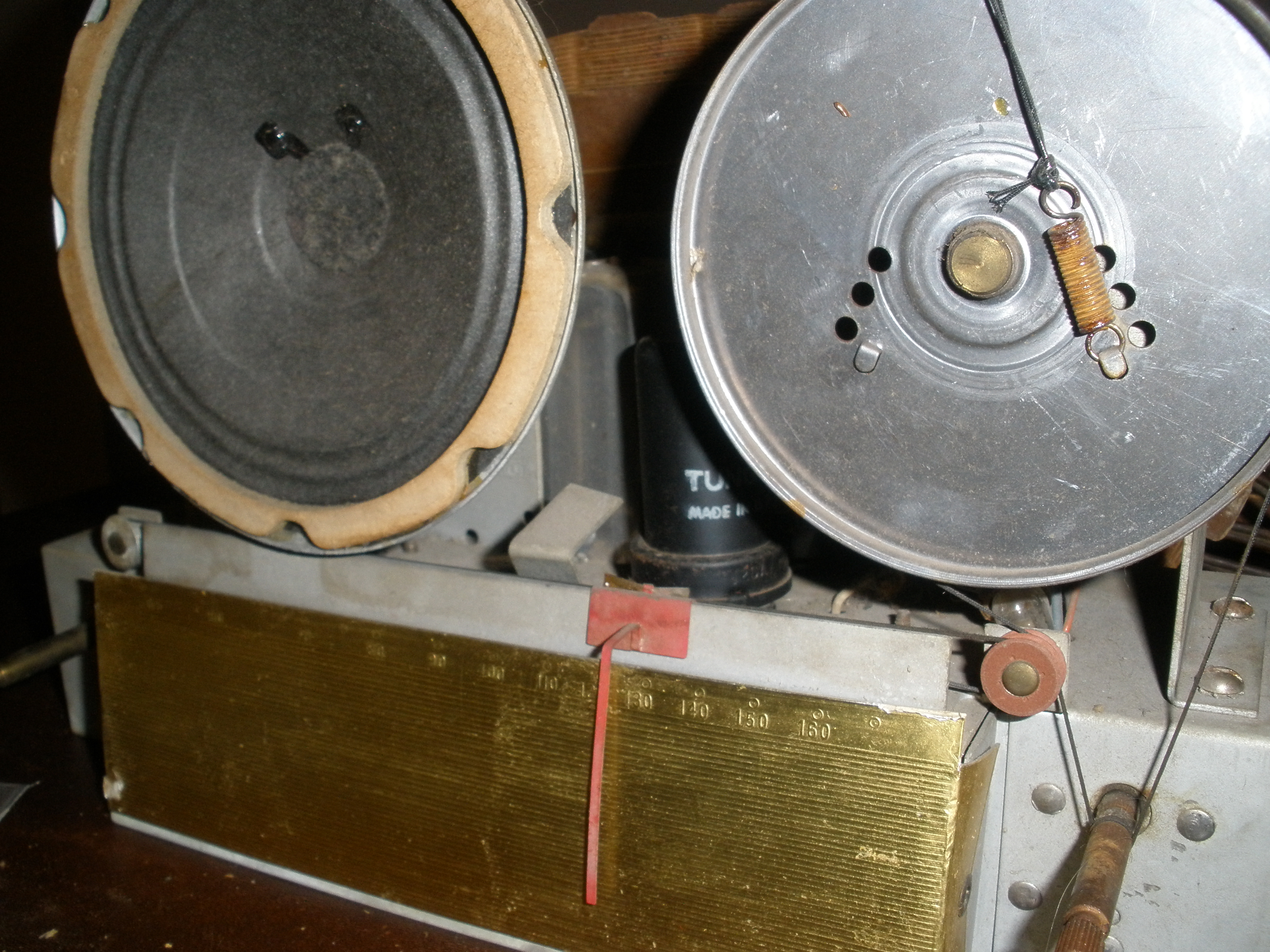
Those are those two var-caps I was talking about. check out that 60-some year old dust ball!
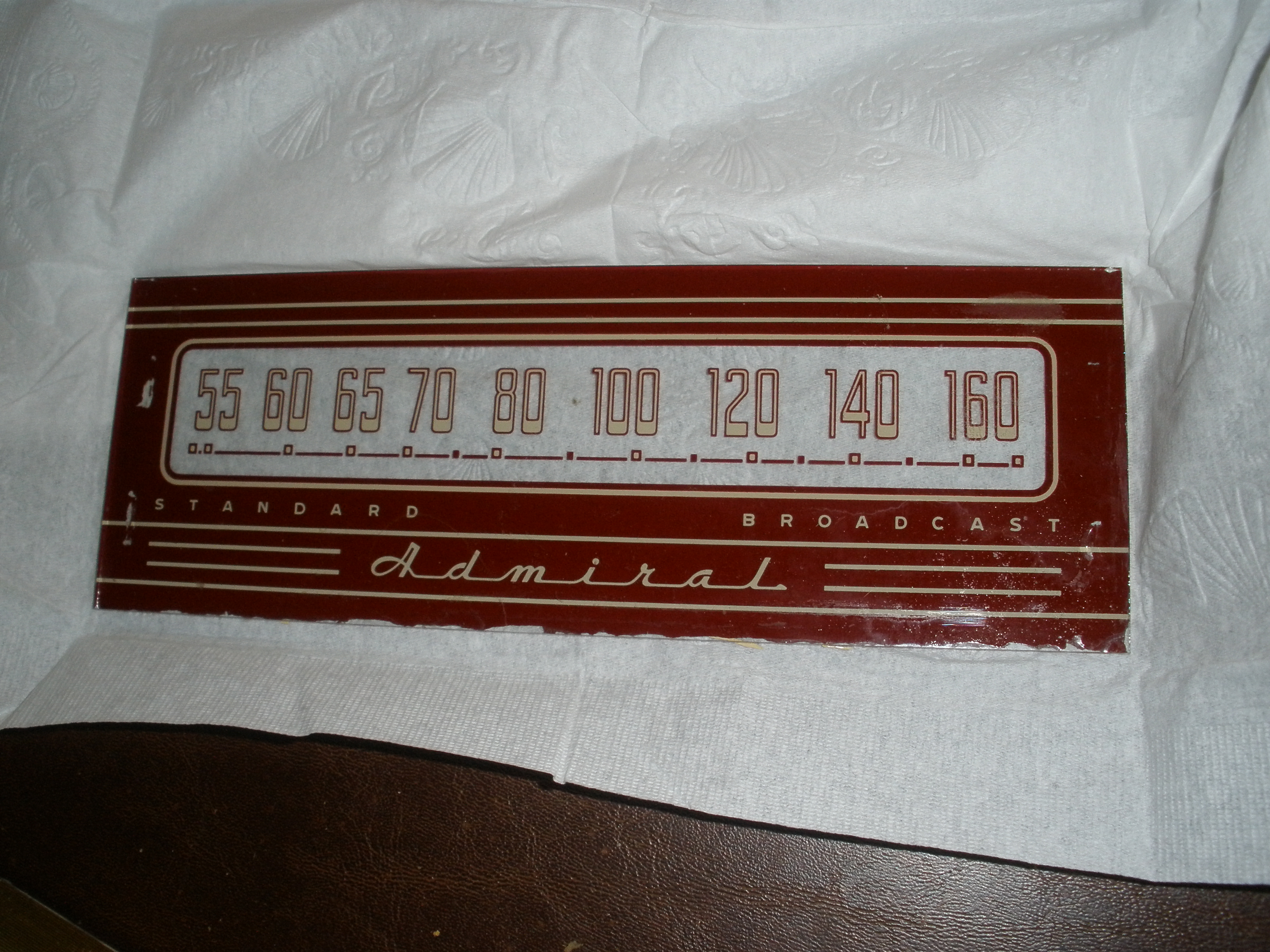
The faceplate of the radio, still looking pretty good
Here is one of the dial knobs. A second one constitutes all plastic in the radio.
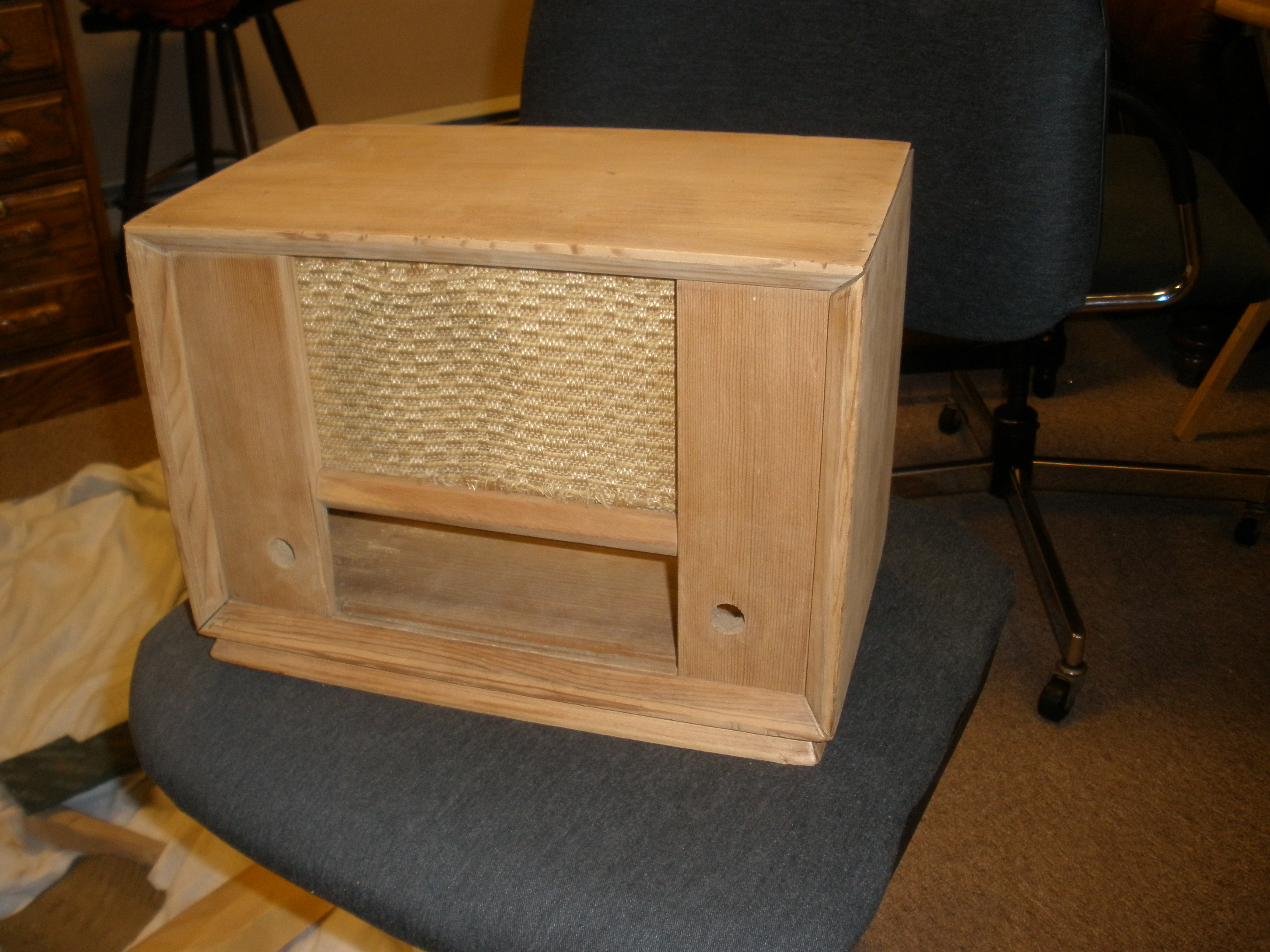
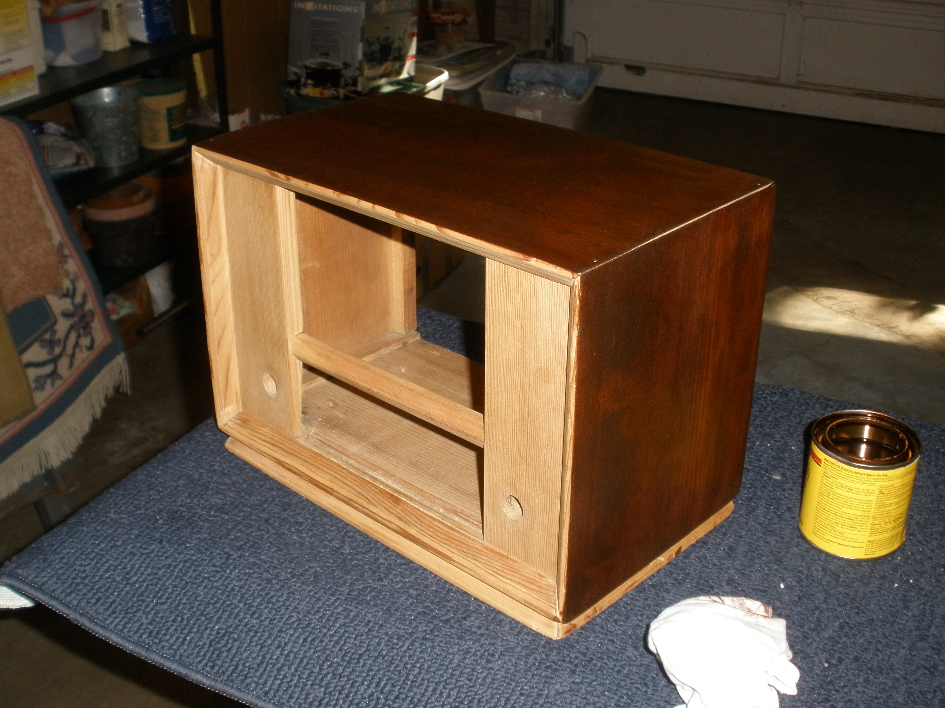
This is part of the wooden case, which I hope to sand down and refinish
Here is the entire schematic. It is set up in three stages: the RF amp, the IF amp, and the base-frequency amps and output. the 2006 ARRL Radio Manual has been helpful to my understanding of the TRF receiver, staged as it is.

The chassis was coated in a thick layer of resilient dust. Here I have re-seated all but two of the tubes, and cleaned out most all of the dust-sludge.
Many fellow computer people I know buy compressed air in a can. An old squirt gun works just as well, and for cheap-as-free. I really don't want to call many of the canned-air people fools, since most of them are good people, but $5 a can? Seriously?
How about that var-cap now? Some squirt-gun air, contact cleaner, and a copious (dare I say, Liberal?) amount of WD-40 to the chassis and pivot-points, and it looks and rides like new!
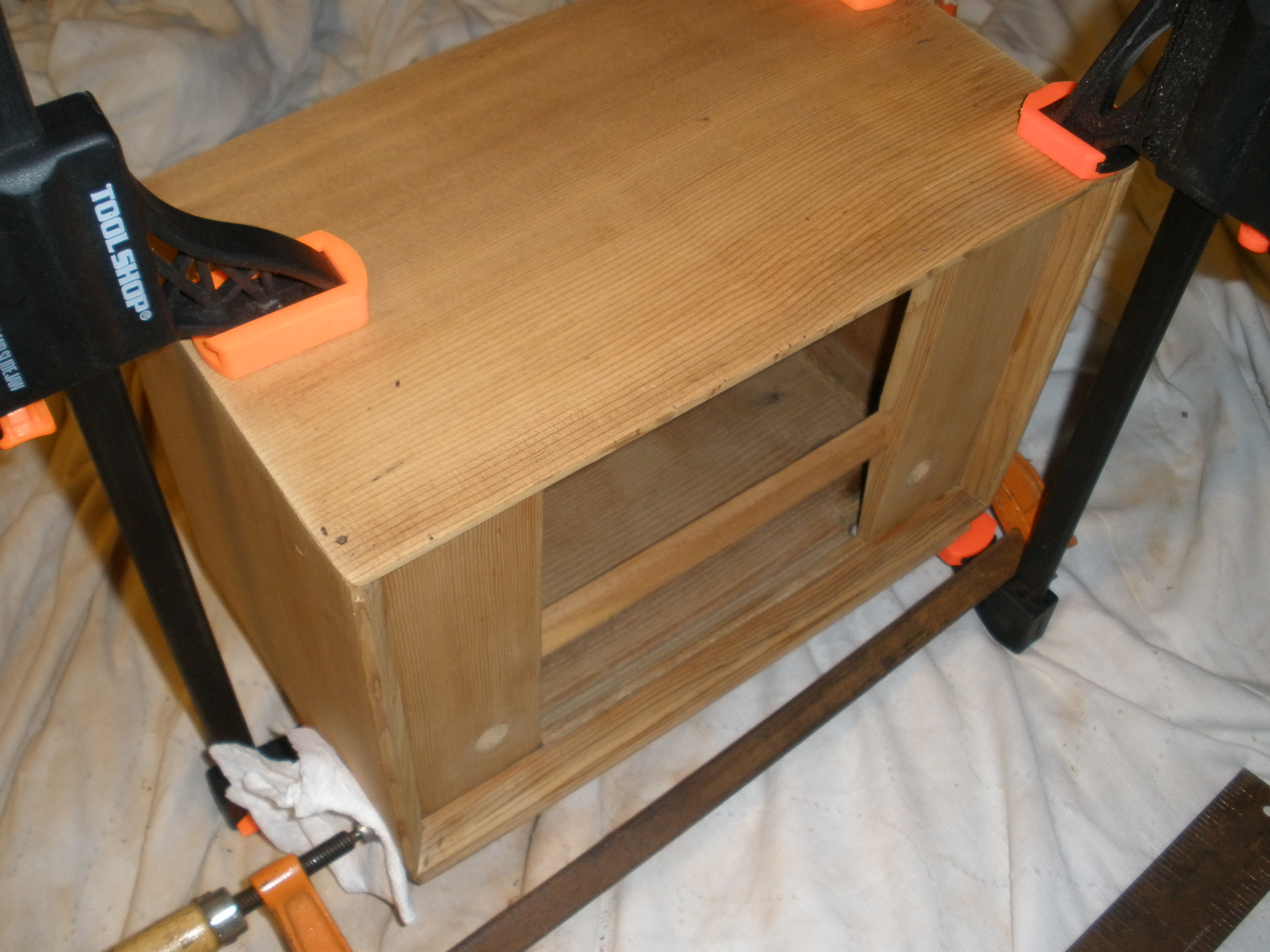
This is the case, mostly sanded and ready to go together.
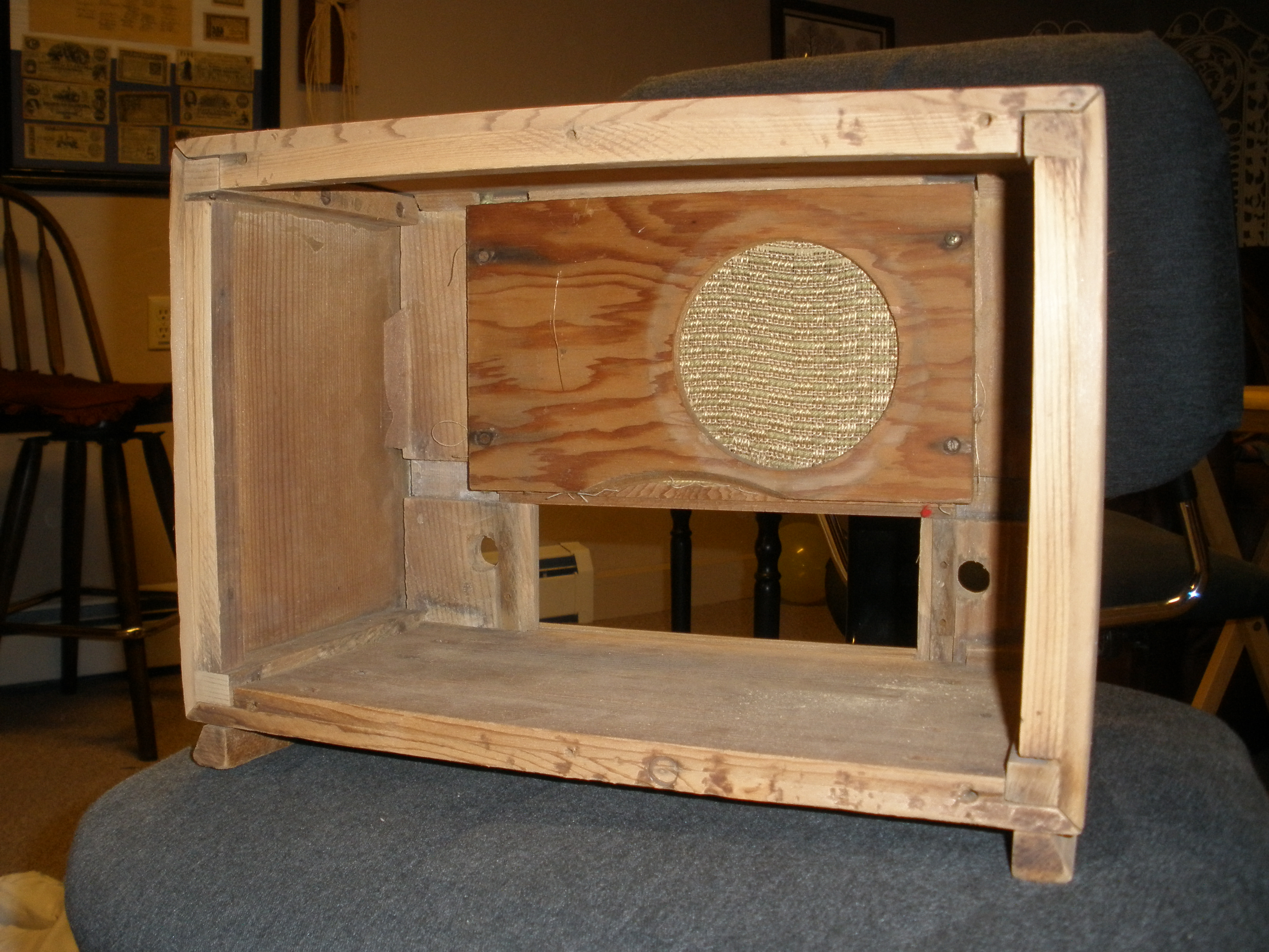
The inside of the case got a minor sanding, and I cleaned the joints will take the glue well.
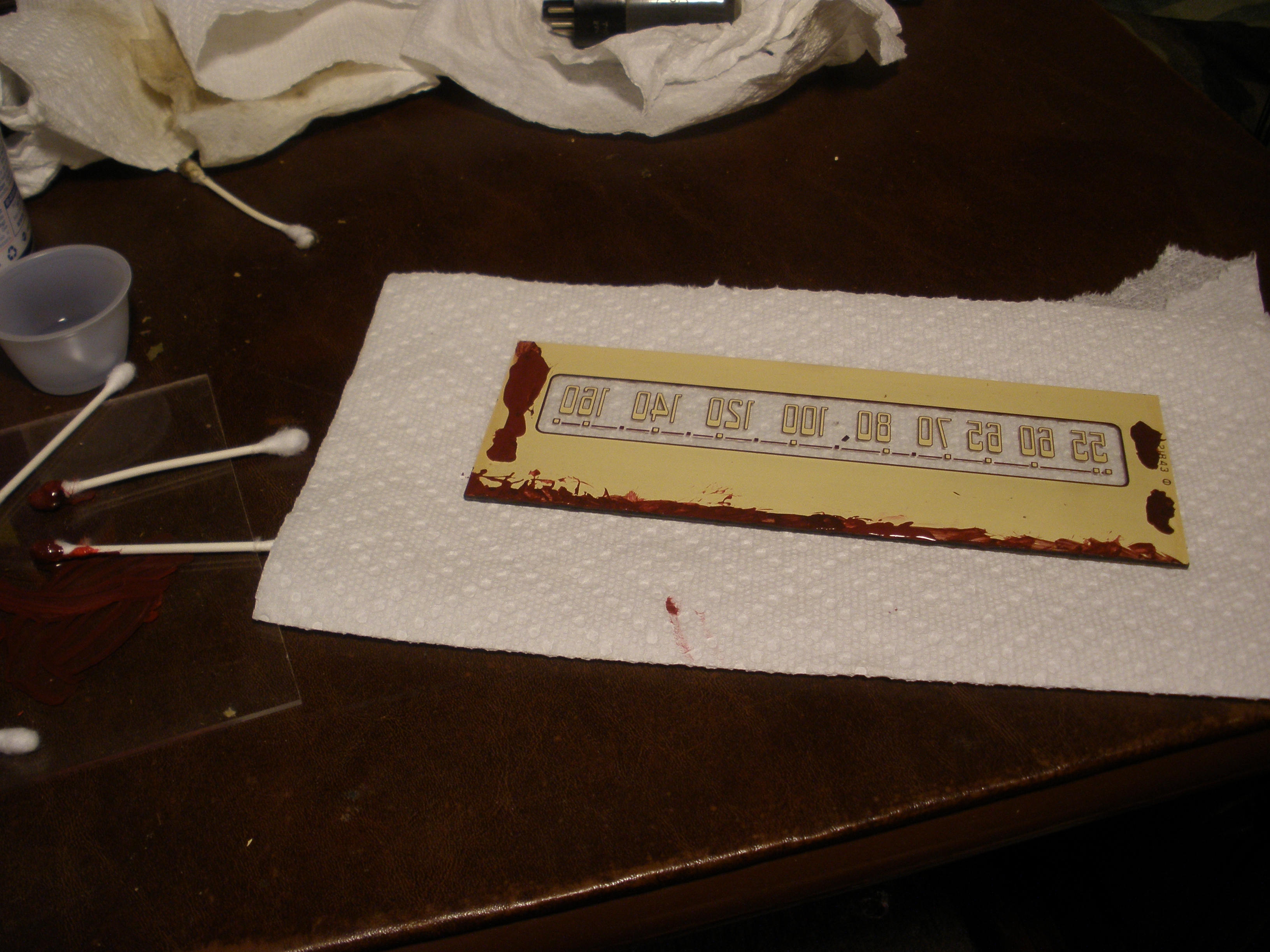
The sticker is on the verge of falling apart. I might lacquer over it so it doesn't crumble off.
The little metal clips that held the glass faceplate in scratched some of the paint off, so I try my best to match the color and cover the chipped spots. The faceplate is upside down here, so don't start mocking my work 'till you've seen the front.
I made sure to check the knob-holes lined up before finalizing the case. The factory must have had wide tolerances on the wooden pieces, and the sanding probably didn't help.
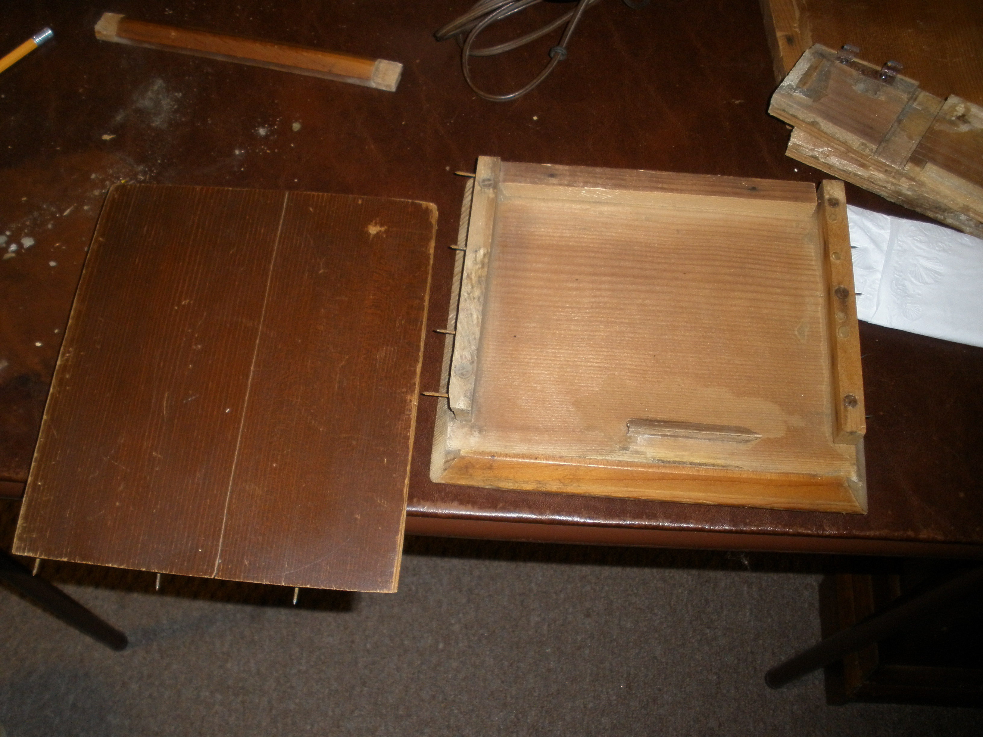
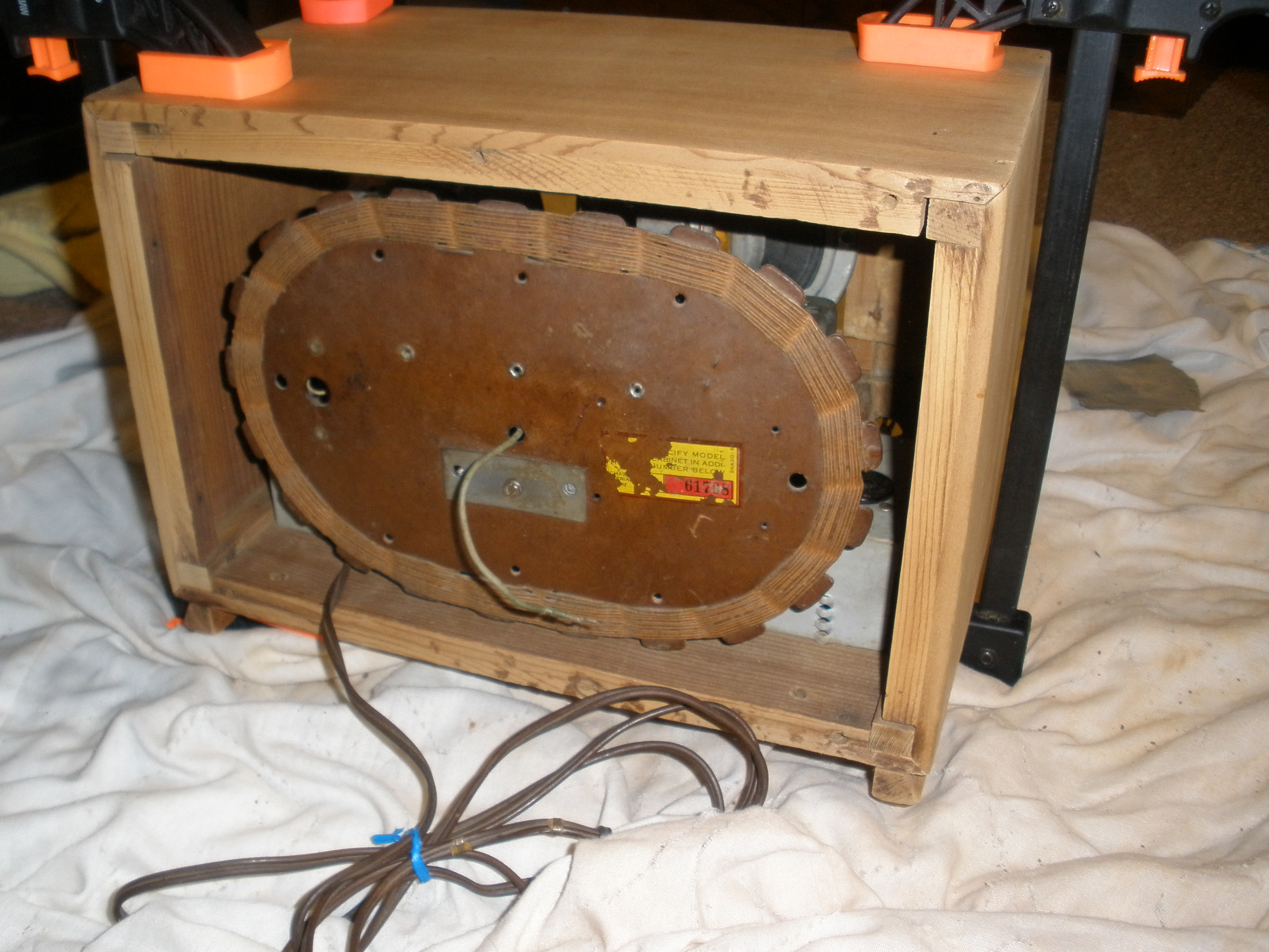
The antenna coil will not be exposed in the final setup, as I plan to make one of those cheap sawdust-board back-pieces common on these old sets.
Thankfully the glass fit nicely into it's hole, and it looks pretty decent, no?
I will leave it overnight to harden and dry. The stain is the thing I'm most worried about, but that can wait. Soon I hope to be back at electrical work, get some "new" tubes, and get the rig working before I put it all in its almost-new box.
This is the Tube Tester readout for the 50L6, the main audio amp. Apparently I was wrong about it being bad, but I still wonder about that little component running trails in the smokey glass interior.
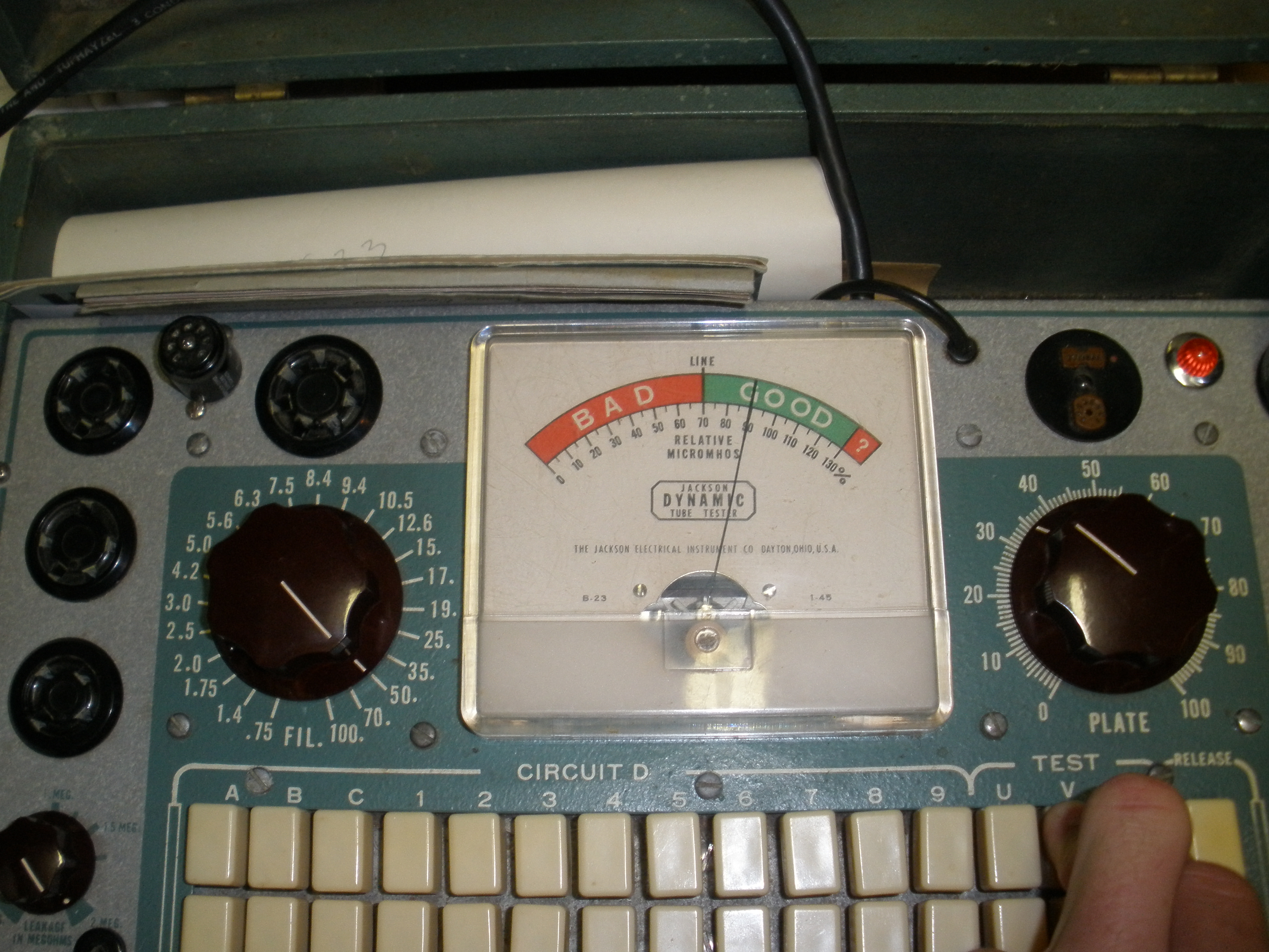
The rectifier tube seems in good condition. All thanks to K0DAS for the use of his tube tester. This is by far the best one I've ever seen, but apparently he has a better one that was loaned out.
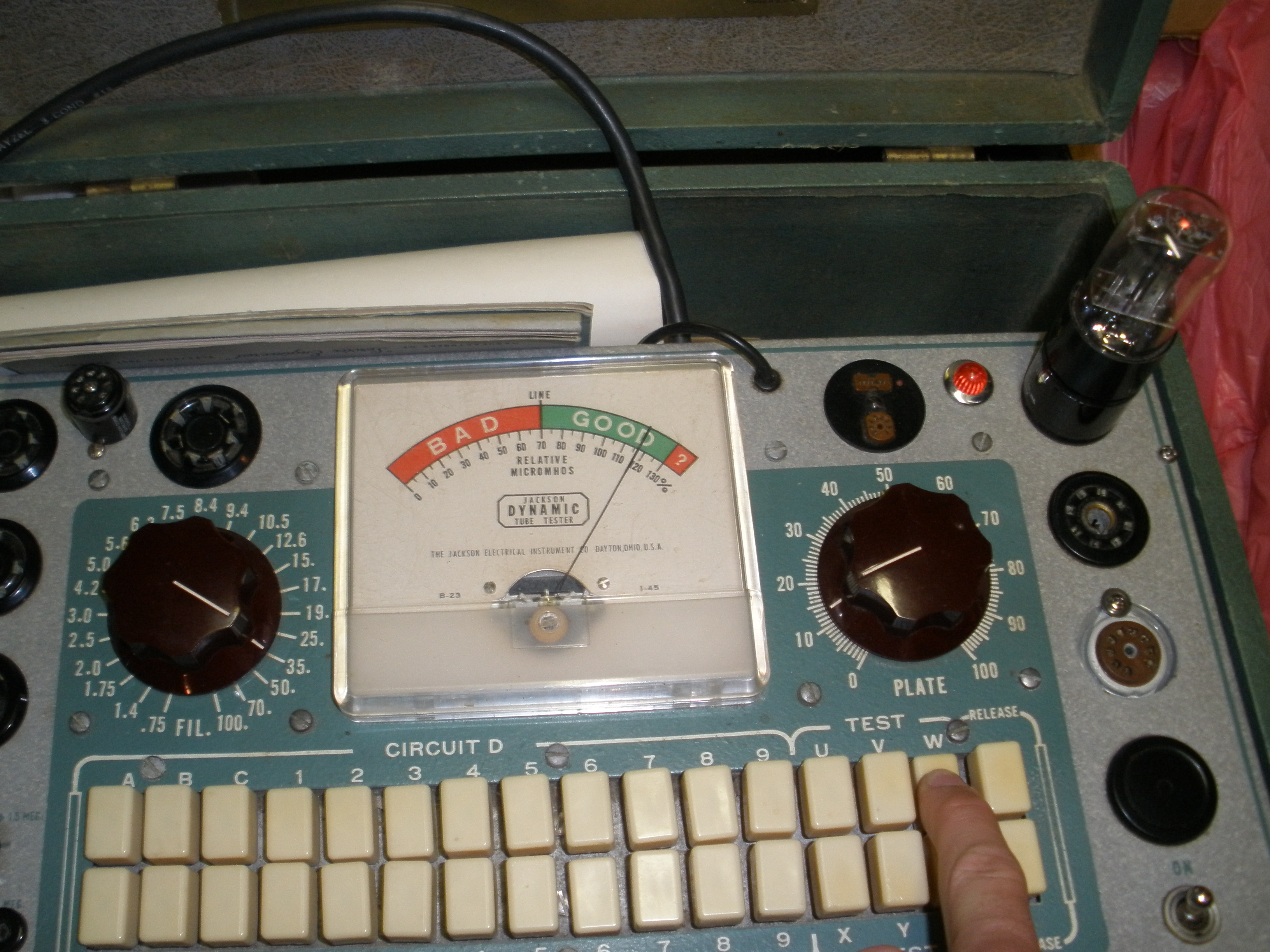
This is the replacement tube for one that went bad. the AF rectifier tube was in the BAD zone for one of the diodes.
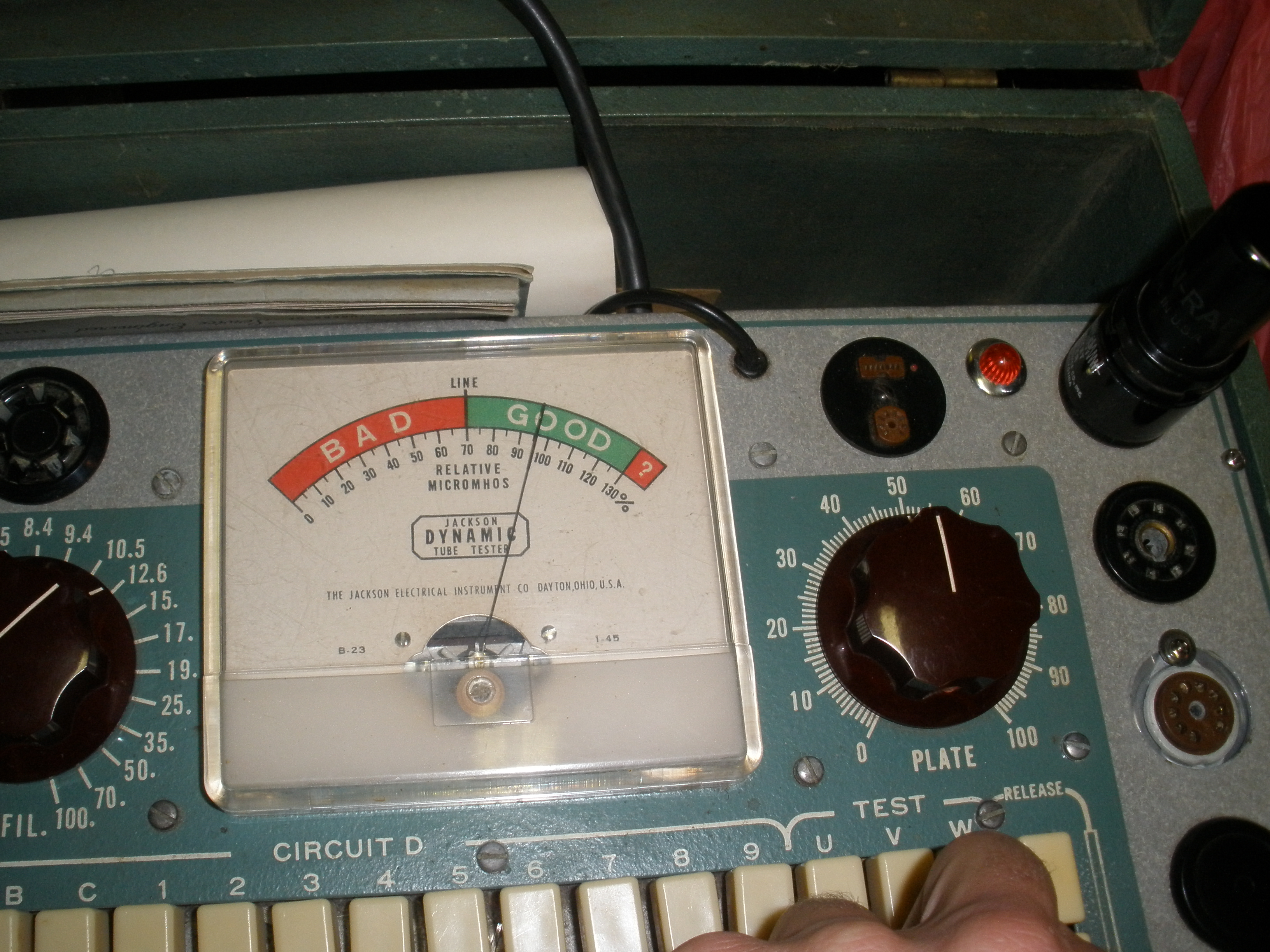
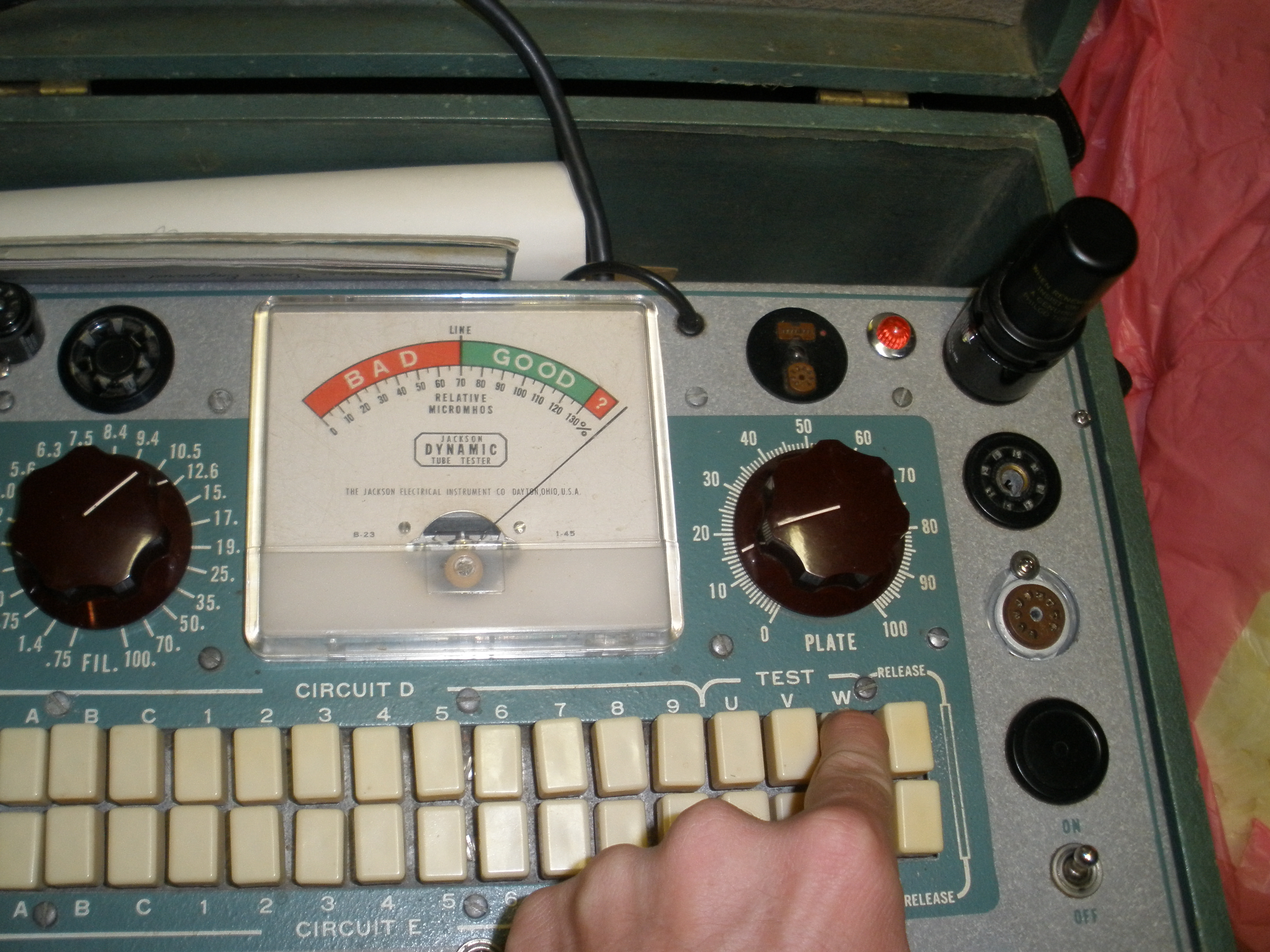
Now this one still confuses me. Supposedly this tube has so much gain that the tester WTFThisShouldn'tBePossible'd, but it seems to be a fine tube.
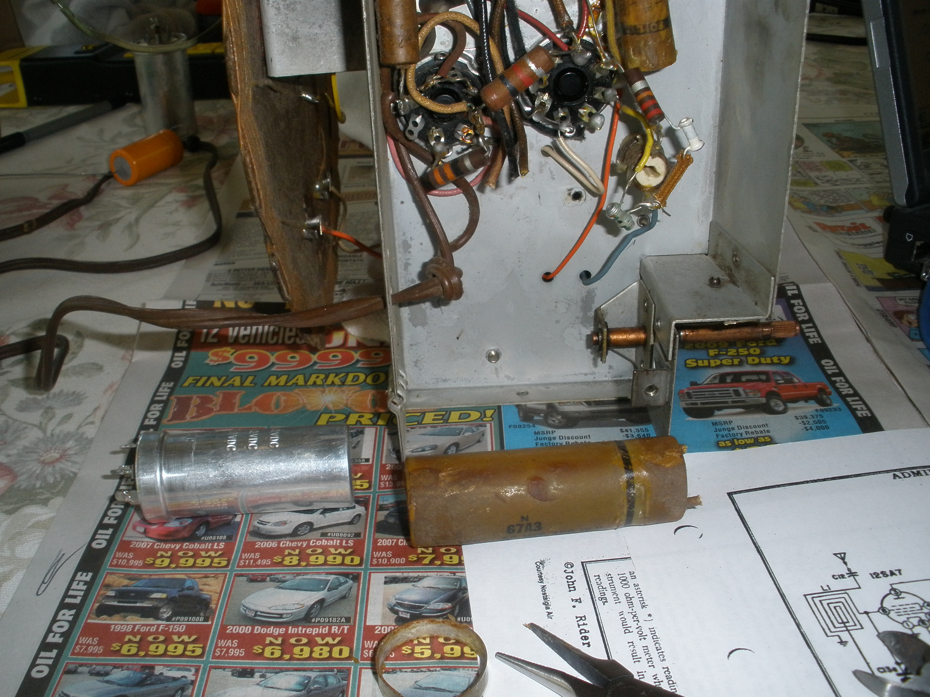
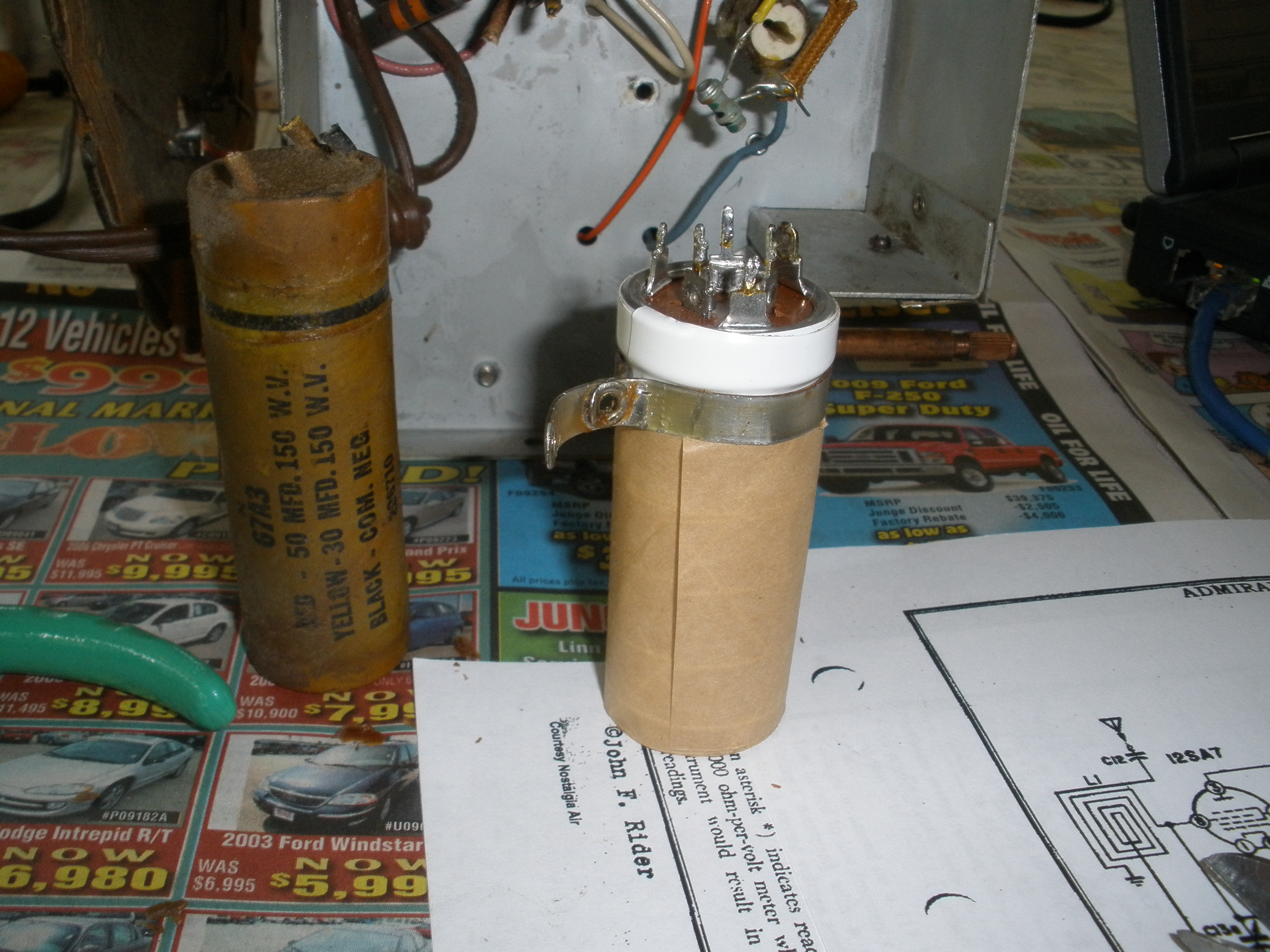
K0DAS suggested replacing this big electrolytic capacitor with a newer one. I guess the chemistry tends to deteriorate after 60+some years.
He gave me a new one, higher capacitance to filter the rectified AC into nice clean DC, that fit the form factor of the old one.
TSo i cut the old one out
I uglied the new one up (partially so the NEG case on the 'Cap wouldn't short to the ground via the bracket.)
It looks more fitting than it would have.
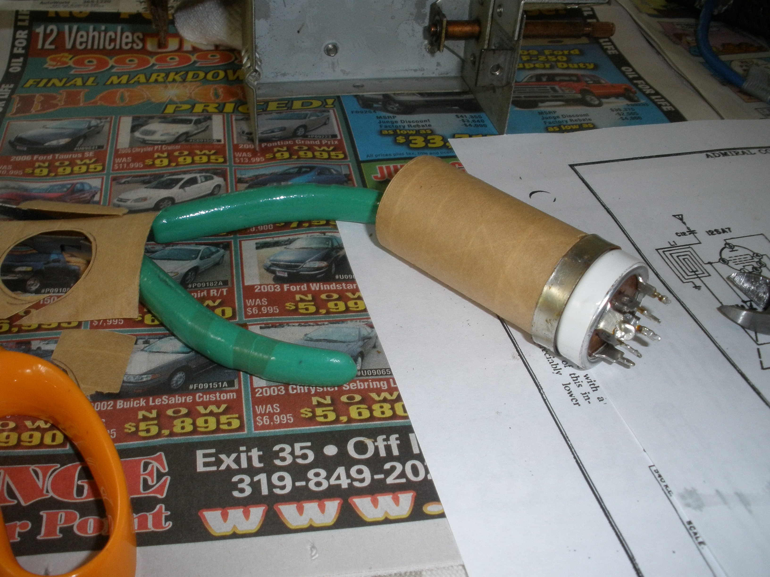
I never stripped cloth-insulated wires before. It wasn't too difficult, and you could take a lighter and burn away the extra strands you don't feel like cutting.

I had to drill a new terminal hole in the 'cap's casing mount, but the soldering went well.
IT WORKS!!! Watch those tubes glow! The dial needs to be calibrated, but the sound is loud and clear. Many thanks to K0DAS for the tubes, testing, and providing the perfect capacitor! Now back to the box...
I decided on a redwood oil-stain, and here is the case mid-staining. I think it looks pretty sharp!
Once I get the case lacquered, front assembled, and innards back inside, this radio will be almost completely restored.
Not yet lacquered, but I wanted to see how it all looked.

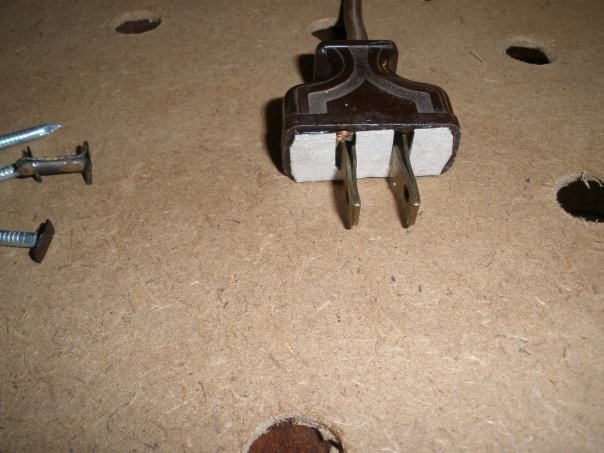
It needed a backpiece, so I found some of this old sawdustboard that will work nice.

I cut holes for the antenna, the AC line, and for ventilation

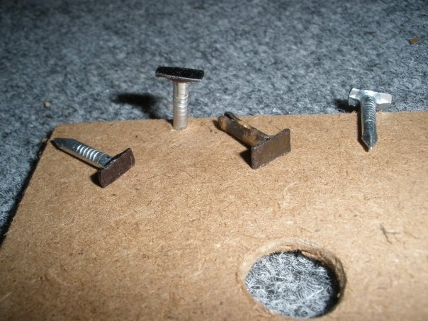
Using nails looks tacky, but I needed something to replace the original tacks, so I made the nails less (or, more?) tacky by bending and breaking off part of each side, like so...
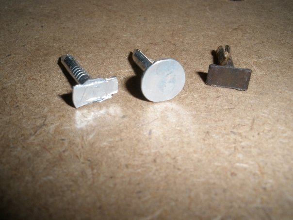
Add a little Sharpie to the ends and they look almost identical to the one original tack I still have, at least from the outside.
To cover the bare exposed AC line screw terminals, I just cut a piece of cardboard.
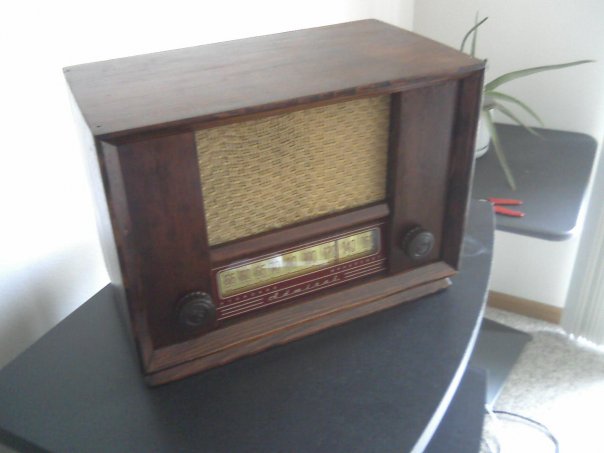
Final Product! It sounds great, especially on the oldies station from Canada in early evening!
Click on the letter for WinLink Email!

2021 AA0CN